Floating Tonearm :
A little very thin strip of rudder aligned parallel to stylus point (Tangential to grooves) fixed at the bottom of container will exhibit resistance to rotational movement. Isn't it ? And a small amount of viscous liquid inside the container will give little more damping. Right ?
Regards.
A little very thin strip of rudder aligned parallel to stylus point (Tangential to grooves) fixed at the bottom of container will exhibit resistance to rotational movement. Isn't it ? And a small amount of viscous liquid inside the container will give little more damping. Right ?
Regards.
Hi Tom,
In your explanation of vibration you are actually describing two very different types of vibrational energy as if they were the same. The two types are bending waves and compression waves (sound waves). My initial comment on the disadvantage of long armtubes was specifically concerned with bending waves. It is very rare to ever see a review or technical articles on the subject of tonearms (or even entire turntables) that distinguishes between the two, in fact it is so rare I have never seen one. In the first post on page 219 of this thread I gave a brief description of each type of vibration and how my design aimed to minimize their effects.
The tuning fork is a classic example of bending waves. The prongs of the fork bend along their length as they vibrate. When you touch the prongs with your hand you are applying damping. In your description you say that the tone disappears nearly immediately. The key word here is NEARLY and is an example of the difficulty in visualizing an audio bandwidth system as mentioned in my previous post. Although it may appear nearly instant the tuning fork may actually continue vibrating for hundreds of cycles before its motion is completely damped and may take tens or hundreds of milliseconds. A ten millisecond smearing of a transient attack would sound very flat.
You mention that the armtube is made of different components each with its own characteristic resonance (resonant frequency). Say you combine two components into a structure. For example a tube with a resonant frequency of 10khz and a rod of the same length with a resonant frequency of 1khz. The rod is fitted snugly inside the tube. A common view is that the tube with still try to resonant at 10khz and the rod at 1khz and will fight each other preventing either from resonating. This is not what actually happened at all. The tube and rod make combined system with its own resonant frequency. What this frequency is will be dependent upon the relative masses and rigidities and will tend to fall between the resonant frequencies of the separate comments. Depending on the properties of the tube and rod the combined system may or may not exhibit greater damping than either of the separate components. The combined system may resonate just as much as either component on its own.
The combination of materials used in the floating tonearm armtube will almost certainly offer greater damping than the composite tube in isolation. You cannot assume that there will be no energy dispatch to the outer tube. The whole armtube will bend and resonate as a single unit. The water will act to further damp bending within the armtube but will be far from sufficient to entirely eliminate resonance.
All tonearms have a fundamental resonant frequency. This is the lowest frequency that the whole arm (including cartridge and counterweight and any other parts) combined as a system resonates. Damping is used to control this resonance and its harmonics. Increasing the resonant frequency of the system has several advantages. Less of the audio bandwidth is above the resonant frequency. There is less energy at higher frequencies to excite the resonance. High frequencies are easier to damp. My approach was to push the resonant frequency as high as possible, above the audio bandwidth. The entire bandwidth is below the resonant frequency. There is very little energy recorded at this very high frequency. As the resonant frequency is not in the audio bandwidth no damping is required at all (my arm actually does have very good damping due to the inherent properties of the materials used).
When you mention the reflection of vibration you are now talking about compression waves also known as sound waves. (Bending waves do not reflect at an interface but are modified by it.) The degree of reflection is dependent upon the impedance of the boundary at which the reflection is taking place. There will be a strong reflection at a high impedance boundary (such as between a solid and the air) and a weak reflection at a low impedance boundary (such as between vinyl and acrylic).
In the floating design the armtube is a single piece that passes from headshell to counterweight via the sphere. The attachment of the sphere and vertical rod do not break the continuous armtube and will have virtually no effect on the transmission of the sound wave along the length of the armtube. You suggest that most of the vibration will be reflected at the interface between armtube and sphere. In fact very little energy will be reflected at this interface. The sphere itself is not substantial enough to create significant reflection and only a small reflection will occur.
The damping effect of the water will have little effect. If you doubt this try this experiment. Take a length of the armtube material or something similar. Press one end against your ear. Hold the centre tightly in your fist, this will apply damping much greater than the sphere floating in the water. Now gently rub the other end with a finger. Even with the tube highly damped by you fist you can still clearly hear the rubbing. Only gently holding the armtube instead of in a fist makes little difference.
The first major interface that a sound wave propagating down the armtube from the headshell will encounter is the counterweight, this is probably where the main reflection will occur. There definitely will be vibration in the rear section of the arm.
This strong reflection from the counterweight is why many tonearm designs have a decoupled counterweight. In these arms there is often a heavy bearing yoke in between headshell and counterweight but still the decoupling of the counterweight makes a big difference.
Thanks for the interesting discussion.
Niffy
@Niffy,
Thanks for your explanation about reflecting waves (second part of your post). I understand your experiment with the help of a tube/rod and you are completely right. It is a bit stupid that I didn’t realize that before because this is the way to listen to the bearings of a combustion engine (I have done it so many times, long long ago).
However, the counterweight of the floating tonearm is not glued to the armtube (it is not a rigid connection). There is a short tube pushed over the armtube and the vertical tube of the counterweight is glued to this short tube. So I can adjust the azimuth, the VTF and the vertical balance with the counterweight. After all - because of your explanation - I have to conclude that I had some luck when I chose this solution.
There is another aspect of the resonances of an armtube: the source of the vibrations. The suspension of the cantilever of MC cartridges is done with the help of a rubber damper and the end of the cantilever tube is fastened into the housing with the help of a “piano string”. (Perhaps this is not the latest type of design but I don’t want to dismantle my cartridge.)
In this way, the vertical and horizontal vibrations of the cantilever are a perfect source of bending waves. And now the question arises about the benefits of splitting these vibrations of the cantilever in 2 independent dampers (left/right channel). The frequencies that represent the music in front of the listener are distributed equal over both channels (the biggest part of all the frequencies). So when I prevent the merging of both vibrations into a single point (the “pivot” of the cantilever) there arise a new situation (in relation to resonances). Instead of a point like source in the direction of the centreline of the armtube, now the vibrations emerge at right angles to the centreline. So all the vibrations that are equal distributed over both channels will eliminate each other when they arrive from opposite directions. That’s a nice idea.
Last edited:
I'm loving the discussion between Niffy and Tom and as an observer I learned so much!
@Niffy, in your critique of long armwand in regard to resonances and bending waves, doesn't it apply to most pivot tonearms and not just the floating arm? It appears the float arm probably does a better job than most traditional pivot arms. If you build a pivot arm, not a parallel tracker, what will your solution be? Does the Dynavector arm's "split-plane" design work as one solution? I know I'm probably offtrack from the linear tonearm topic but ALL tonearm has an armwand, short and long, and I'm curious in different solutions and approaches. Thank you and Tom for making this thread continuously entertaining!
@Niffy, in your critique of long armwand in regard to resonances and bending waves, doesn't it apply to most pivot tonearms and not just the floating arm? It appears the float arm probably does a better job than most traditional pivot arms. If you build a pivot arm, not a parallel tracker, what will your solution be? Does the Dynavector arm's "split-plane" design work as one solution? I know I'm probably offtrack from the linear tonearm topic but ALL tonearm has an armwand, short and long, and I'm curious in different solutions and approaches. Thank you and Tom for making this thread continuously entertaining!
@Hiten,
Sorry that I didn't answer your question/suggestion. I overlooked your post. Water inside the sphere is nice for more damping. However, damping is not the problem because the tonearm works fine. Besides that, the water inside the sphere will evaporate too and I am afraid that in this wet environment the roller bar will get a thin layer of algae. Your idea of a rudder will not solute a problem. The rotation of the sphere is necessary to get the tip of the stylus at right angles to the spindle of the platter. Fortunately, water has a very low friction so there is hardly any resistance during the rotation and the transport of the sphere from one side to the other side of the bowl with water.
Sorry that I didn't answer your question/suggestion. I overlooked your post. Water inside the sphere is nice for more damping. However, damping is not the problem because the tonearm works fine. Besides that, the water inside the sphere will evaporate too and I am afraid that in this wet environment the roller bar will get a thin layer of algae. Your idea of a rudder will not solute a problem. The rotation of the sphere is necessary to get the tip of the stylus at right angles to the spindle of the platter. Fortunately, water has a very low friction so there is hardly any resistance during the rotation and the transport of the sphere from one side to the other side of the bowl with water.
Hi Tom,
It looks from your description that you have at least partially decoupled the counterweight which should definitely reduce any reflection at this point. One point I failed to mention that a smaller counterweight will tend to reflect less than a larger more massive one. The overall design and method of mounting will also affect this. The small counterweight of the floating arm should be a benefit in this respect.
You are correct that the motion of the cantilever is the source of the energy that will cause the bending modes. The amount of energy that is transmitted via the cartridges suspension is dependent on the compliance of the cartridge, the level of damping of the cartridges suspension and the driving frequency. Back in Page 207 post 2063 I described a bit about effective mass. This was concerned with the relative amount of movement between the groove and cartridge body at frequencies below the arms resonant frequency. The method of energy transfer to the cartridge body/arm is the same at higher frequencies, at and above the bending mode resonant frequency, but things get a bit more complex. Below resonance the groove and cartridge body move in phase, at resonance they have a 90° phase shift and above resonance they have a 180° phase shift. To make matters worse the phase continues to change coming in and out of phase at each harmonic. Below resonance the cartridge is controlled by the effective mass, at resonance and above it mainly controlled by rigidity and damping.
As the two channels are recorded at right angles to each other I don't think it would be possible to use one channel to cancel the energy transfer of the other. In many cartridges the vertical and horizontal compliance and damping are actually different. Nice idea though.
Hi DD.
Absolutely. The effects of the bending modes and resonate frequency do effect pivoted arms. The reason why I ended up making a linear tracking tonearm was so that I could reduce arm length in order to better control arm resonance. You can't make a very short pivoted arm without ending up with massive lateral tracking error. Well you can. As you correctly suggest, the dynavector is a pivoted arm with a short armtube. Their reason for making the arm short is the same as mine and apparently this is a very good arm. My critique of the long armtube of the floating arm was not specific to this arm but to all long armtubes. I pointed out this aspect of the floating arm design as it was one aspect that varied significantly from the arms shown so far in this thread, most of which are less than half the length. The total length of the floating arm is about the same as a 12" pivoted arm. The floating arm should however offer lower lateral tracking error, better damping and less compression wave reflection from the counterweight.
Niffy
Personally, I think implement is equally important. Of course, short arm eliminates the possibility of arm resonance. However, even for short arm, implement is important, too. My latest air bearing arm reflects my own experience with implementing short arm. I used lead, aerospace aluminum and magnesium. It is the most natural sounding and best sound stage arm I have ever built so far. I find that polycarbonate is not an ideal material for tone arm(neither for turntable?). Clear Audio uses polycarbonate. Polycarbonate has certain sound signature which is not desirable at least for my taste. Magnesium is probably my most favorable material. The structure of short arm is important, too.
Last edited:
Hi Jim,
You are of course correct. Making the arm short is not on its own a guarantee of high sound quality. The overall shape of the arm, the materials used (and where they're used), mass distribution, bearings, the structure supporting the rail and many other design considerations are all important. Magnesium is a very good material for use in tonearm designs and has been used in many high end arms. I think the best possible material would probably be beryllium as it has the highest rigidity to density ratio of any material other than diamond, has the highest speed of sound of any material, good thermal stability and damping properties not dissimilar to magnesium. Unfortunately it is highly poisonous. My material of choice was a carbon composite/balsa sandwich. Shortening the armtube is a step in the right direction, though this does introduce other design considerations. The advantages of the short arms outweighs these.
Niffy
@Niffy,
I made a design for a phono cartridge that’s quite different. The movements of the stylus are detected just above the stylus. Now the cantilever is just some kind of “rope” (tube) to withhold the stylus to be pulled away by the friction of the groove. Each channel has its own magnets and damping. But I was concerned about the vibrations. However, now I understand that I can eliminate a lot of vibrations with a careful design of the body of the cartridge.
I made a design for a phono cartridge that’s quite different. The movements of the stylus are detected just above the stylus. Now the cantilever is just some kind of “rope” (tube) to withhold the stylus to be pulled away by the friction of the groove. Each channel has its own magnets and damping. But I was concerned about the vibrations. However, now I understand that I can eliminate a lot of vibrations with a careful design of the body of the cartridge.
Thanks Tom,
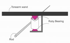
didn't knew that rotation of sphere (dish) aligns the stylus and friction holds the pivot along the rod. This is brilliant idea.")
Would a bearing where the rod touches the pivot help in reducing friction ? Kindly see attached pic. (Pardon for rather crude diagram) the bearing can be firmly held if we use plate spring at bottom to hold it in place. For example like this.
Best regards
didn't knew that rotation of sphere (dish) aligns the stylus and friction holds the pivot along the rod. This is brilliant idea.
Would a bearing where the rod touches the pivot help in reducing friction ? Kindly see attached pic. (Pardon for rather crude diagram) the bearing can be firmly held if we use plate spring at bottom to hold it in place. For example like this.
Best regards
Attachments
Hi Tom,
Designing a cartridge is not something I have personally contemplated though I have studied them in some detail. Mainly looking at how they interact with and transmit energy to the tonearm. Your brief description sounds like you are not using a cantilever. I think that Decca made several cartridges like this. As your cartridge is mechanical (it uses a physical stylus) it will still have to have a suspension of a certain compliance. Coupled with the damping you mention and the mass of the cartridge body/arm effective mass this will create a spring-mass-damper system the same as any other cartridge. This will still result in a transfer of energy to the tonearm. This is unavoidable in a mechanical system unless the cartridge is decoupled from the tonearm. Decoupling the cartridge creates another spring-mass-damper system between the cartridge and arm with its own resonant frequency. This would have to be below the audio bandwidth in order not to place a resonance in the audio bandwidth. Decoupling a cartridge in this way is difficult to implement and counterproductive.
Oops run out of time to write more right now.
Niffy
@Hiten,
You are right, a bearing is much better. So I have made a bearing from a low voltage connector and a stainless spoke. See this picture. The short peace of the spoke is glued into the outer tonearm tube.
@Niffy,
It is difficult indeed. But I will give it a try. Maybe in January.
You are right, a bearing is much better. So I have made a bearing from a low voltage connector and a stainless spoke. See this picture. The short peace of the spoke is glued into the outer tonearm tube.
@Niffy,
It is difficult indeed. But I will give it a try. Maybe in January.
Hi again,
Got cut short in my last post.
Virtually all commercially available cartridges have bodies that are made of a rigid material that usually also have good self damping properties. The aim of these bodies is to couple the generator as solidly as possible to the tonearm without allowing any unwanted resonances between the two. There are several aftermarket cartridge decoupling devices available. In certain circumstances where there is a mismatch between arm and cartridge or a particularly lively arm they may be beneficial. They will definitely make the sound different but not normally better. Cartridge manufacturers put a lot of work into developing their products. If decoupling of the cartridge was beneficial it would be built into the cartridge.
Re your post that arrived between the two parts of mine. Definitely have a go at making a cartridge you might have a game changer. It's something that is way beyond my capabilities.
Niffy
Last edited:
@Niffy,
It is way beyond my capacities too if the cartridge is identical to a traditional MC cartridge. Fortunately it is quite different. The most difficult job is the alignment of the stylus with the coils (100% symmetric). When this is perfect done, the channel separation of a phono cartridge can reach about 50 dB. Thus I have to find a trick to do this job in a controlled way (maybe with the help of a laser beam and magnifying mirrors).
This schematic drawing shows both dampers (red and blue). Vibrations from both dampers that are equal to each other will vanish, the other persist. However, this is not 100% reality. Moreover, the remaining vibrations of the left channel will influence the right damper and visa verse. So there is a lot to think about. In January ;-))
Sorry to all, this was off-topic...
Hi Tom,
A good binocular scope is expensive.
Adapting the light source of your existing scope with the addition of a polarized filter shouldn't be very costly. By rotating the filter you should be able to find a setting that allows you to see the facets of the stylus more clearly than under non-polarized illumination.
Niffy
I think that Decca made several cartridges like this. As your cartridge is mechanical (it uses a physical stylus) it will still have to have a suspension of a certain compliance. Coupled with the damping you mention and the mass of the cartridge body/arm effective mass this will create a spring-mass-damper system the same as any other cartridge.
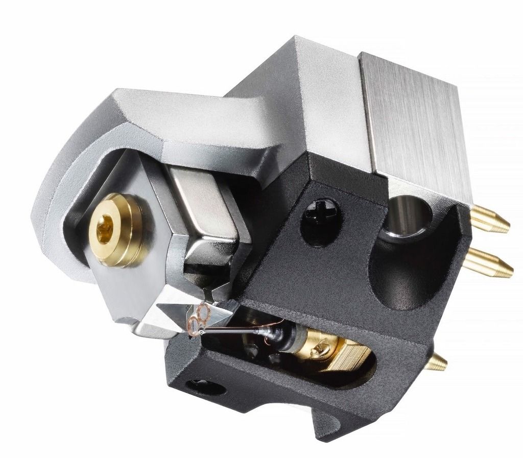
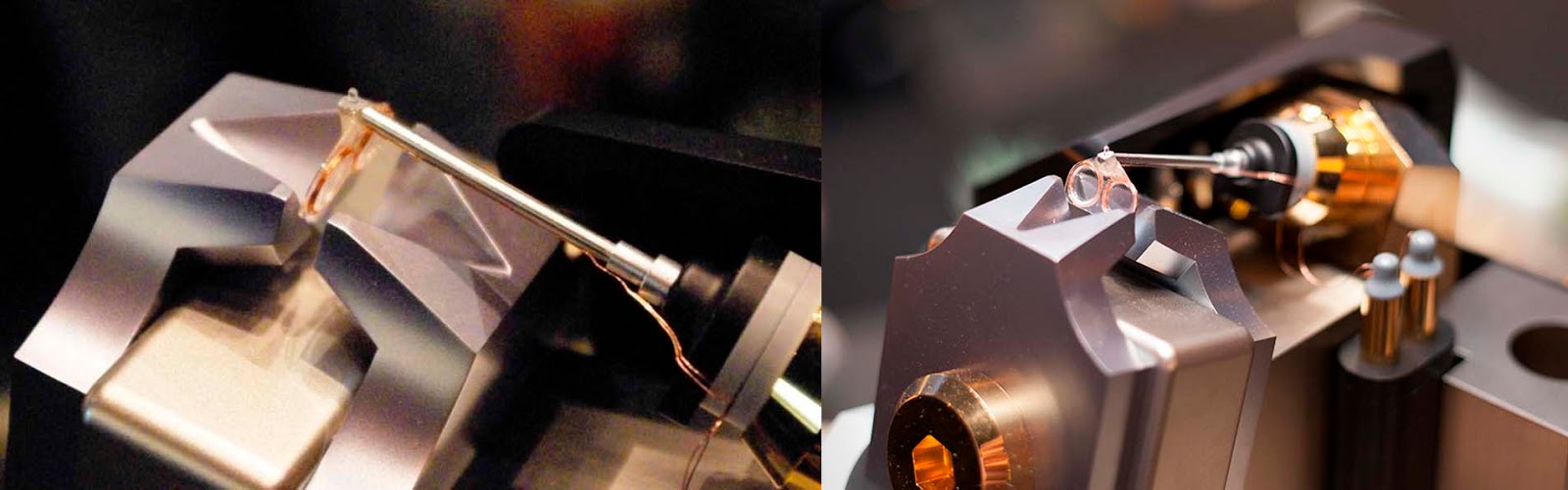
In recent production, the newly introduced Audio Technical ART-1000 is similar. As you can see the coils are right above the stylus but it has a rather long cantilever from stylus to the suspension. I'm curious what material is the cantilever. Reportedly it's very hard to make and only one person knows how to make the coils and install them properly.
Fascinating stuff!
Hi DD,
The amount of cool stuff you find never ceases to amaze me. My initial reaction was the same as the guy in the video, high tip mass and long cantilever, surly not. But as the coils are attached right at the stylus and not at the other end of the cantilever the negative effects should be alleviated. Nice find.
Niffy
- Home
- Source & Line
- Analogue Source
- DIY linear tonearm