I don't know if its magic, however it is where many of my constructions of this type have ended up!
I recall i got one to 38gms once, but they seem to benefit significantly from rigidity so i don't fight for every little bit, maybe i should?
There are opportunities in mine with any of the aluminium parts being changed to carbon, although i have never tried the running surfaces in carbon although others have...........
Right now i am working at measuring the frequency response. i have measured something but i don't believe its representative of what is happening. i dont know where, current suspect is the record itself! - or the process used.
I suspect that because I have measured a completely different chain as well and ended up with a similar result, so a commercial PTA/TT, AT 95 integrated amp and Behringer, shows the same fall away. so far i tested the Behringer on its own and that shows dead flat response (in my terms!)..........more follows
Attachments
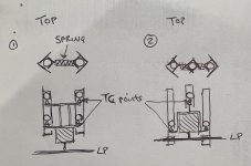
Sorry Mike it was a little vague! See sketch. A linear rail in the z axis. Balls prevented from moving down the channel by TC points which are connected to the head shell. If set up correctly, the bearings should rise in unison with the vee channel and not ride on the TC points at all. A perfect scenario would be that the cartridge weight equals the TF but that is virtually impossible to achieve. Therefore a CW would be needed, maybe your new spring idea?
S.
S.
Attachments
Hi Sether, beginning to understand the idea now! - thanks.
I took a simple pragmatic route when i originally saw Carlo's wonderful invention in little Casey, and it seemed obvious to me to not ask the paralelogram to cope with the whole rail set but only the cartridge end.
I later learnt that Carlo considered that idea already, and i never built any LC variant as i suspect its way too difficult for me.
Subsequently numerous ideas for the vertical motion have been tried by me and others but none as yet for me successful in maintaining the correct orientation of the cartridge to the disc throughout all the ranges of motion, good coupling, removing the lever load from the stylus around whatever points it might act.
Scissor lifts and all sports have been looked at closely!
Your sketch may well work, but all my constructions depend on hand tool tolerance for construction, hence i like my three legged lateral rails where gravity will ensure consistent close contact and small deviations are not critical. The paralelogram also allows reasonably accurate parts to be tuned in final assembly with the little set screws, i could never build to tight enough dimensional accuracy without that adjustment and a bit of springiness.
So its a mixture of the route i started on and pragmatic choices, and as you will have seen recently cost is a factor as well. i just sort of like the idea that i might have made a fine tone arm at very low cost, although current measurement results may tell everyone that's rubbish!!!
I have recently measured my commercially purchased set up as a check and that doesn't measure well either in this frequency response test, which suggests that the measurement procedure i use may be at fault........i hope so and will investigate further.
M

I think your design is very successful, it’s been sticking in my thoughts which is why I asked the question about the parallelogram..very intriguing! As you know I’m pursuing the double rail approach but I find it fascinating in how many ways an LTA can be achieved. Really enjoying this project!!
S.
S.
#5339 - my compliments, Sether - those of an apprentice turner even before of a TA diyer.
Even more that for the incredible precision achieved with such exotic materials as for how you carried out the final inspection - the good old way
Turning between the centers + the cat's whisker are what have brought us here over the millennia. Geometric trueing available by the simplest means.
#5335 virtually impossible to achieve
yes, completely fool - I called Moon Ready what posted long ago: just with moon gravity could work- this was an attemp to bypass the problem - completely fool
Attachments
Last edited:
Thanks Carlo. Interesting concept, fascinating!
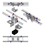
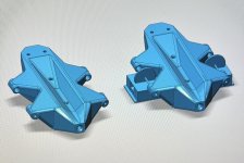
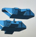
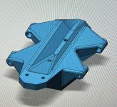
Carriage design completed ready for proofing with a 3d print. I’ve included 4x ballast chambers all centred around the pivot point. This will hopefully allow accurate setting for COM. Counter weight, which looks like an exhaust pipe, runs through the axis of the stylus to pivot point to simplify TF adjustment.
S.
Attachments
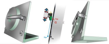
Yes , just a concept; useless as concept cars. But sin alpha seems the only way to get the right VTF in such arrangements.
Carriage -- I' ve made only one 3D printed PLTA, the 3DToy (is it still diying?). The printed PLA is really effective with resonances (stethoscope check )
but sounds different from what we're used to (alu, CF etc.). An immersion in diluted white glue + epoxy finish may help
c
Carriage -- I' ve made only one 3D printed PLTA, the 3DToy (is it still diying?). The printed PLA is really effective with resonances (stethoscope check )
but sounds different from what we're used to (alu, CF etc.). An immersion in diluted white glue + epoxy finish may help
c
There’s some CF filled filament which I might have an experiment with. There’s so many variations of PLA which differ from manufacturer to manufacturer. Some pliable and print well others hard and slightly more brittle. There’s also some experimentation to have with the type of infill pattern within the form.
S.
S.
Thanks Carlo. Interesting concept, fascinating!
Carriage design completed ready for proofing with a 3d print. I’ve included 4x ballast chambers all centred around the pivot point. This will hopefully allow accurate setting for COM. Counter weight, which looks like an exhaust pipe, runs through the axis of the stylus to pivot point to simplify TF adjustment.
S.
If I were you I would use a similar CW arrangement as @niffy, where the CW is attached to the bottom of the carriage structure. If you add a CW hanging off the back you have a structure that has the potential to resonate
If the tube was to remain hollow then this potentially could resonate. My plan is to tap the hole and use a stainless grub screw as the CW. The tube cannot resonate if it’s solidly plugged, the outer wall of the tube is also conical. Having the CW axial through the pivot point to stylus allows the much higher accuracy in setting TF. A nut sliding in a slot is IMO prone to cam out as tightened and move in an uncontrolled way. Niffy might be able to shed some light on this design decision. Having the CW hung at the bottom of the carriage is perhaps a way of lowering COG but if the CW is moved off axis there might be a detrimental effect of a radial force, therefore affecting TF when pivoting.
S.
S.
I did quite a lot of experimenting with CW and levers, i know its a completely different set up, but, for tracking, a light weight on a long lever was always better than a heavy weight on a short lever, so those principles have stayed in my executions.
If the tube was to remain hollow then this potentially could resonate. My plan is to tap the hole and use a stainless grub screw as the CW. The tube cannot resonate if it’s solidly plugged, the outer wall of the tube is also conical. Having the CW axial through the pivot point to stylus allows the much higher accuracy in setting TF. A nut sliding in a slot is IMO prone to cam out as tightened and move in an uncontrolled way. Niffy might be able to shed some light on this design decision. Having the CW hung at the bottom of the carriage is perhaps a way of lowering COG but if the CW is moved off axis there might be a detrimental effect of a radial force, therefore affecting TF when pivoting.
S.
Everything resonates, a weight on a rod will bend like a wet noodle at its resonant frequency. If you can ensure the FR is at the top of the audio band you will better off and that will depend on the rigidity and length of the rod and mass of the CW. I've had no issues adjusting VFT. There is a washer under the bolt head and my brass CW does not move when the bolt is tightened. VTF varies more due to the wheels sliding on the rails.
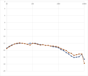
With great help and patience from very generous advisers i have plotted a frequency response that looks like it might be representative.Right now i am working at measuring the frequency response. i have measured something but i don't believe its representative of what is happening. i dont know where, current suspect is the record itself! - or the process used.
I suspect that because I have measured a completely different chain as well and ended up with a similar result, so a commercial PTA/TT, AT 95 integrated amp and Behringer, shows the same fall away. so far i tested the Behringer on its own and that shows dead flat response (in my terms!)..........more follows
I guessed that my commercial equipment probably could produce a reasonable output so i used that in this case, and that the measuring procedure was probably wrong not the performance of the equipment.
I checked and changed all the individual parts to no avail.
All the early curves on the graph showed similar trends.
It seems like the computer input level was set too high and clipping the signal, so whatever equipment i measured all showed the same higher frequency fall off.
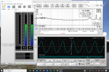
This is all from the vinyl check test record which has 35 tones across the range and i simply played that and recorded the levels.
The early tests of different equipment chains all showed the falling response, even though the trend was as expected with the capacitance change shown in the red curve.
Finally with the change to the computer input level i measured the green curve.
At the higher end there is some rapid variation of the levels when the tests are done so i would say i could not be certain of the highest 4 points on the graph.
I hope to find a solution for this as well.
Then, finally, i can go back and consider whether it guides me in development of the RTA! - which was the ambition.
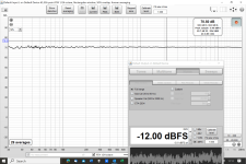
The set up was playing the output of the Phono Pre into my ADC into the computer and using REW i set the screen as pic attached and recorded the values, then plotted the graph.
All ideas welcome, hope its interesting!
M
Attachments
I agree, everything resonates. I can’t see the difference between the unused portion of the nut/bolt slot, which is open and could suffer from resonance and a conical tube buried within a triangulated structure, which IMO is much stiffer. I would be interested if anyone knows of a way to test materials for resonance as I’ve trawled the web for information regarding 3d prints and resonance and as yet there are no studies - just strength tests?Everything resonates, a weight on a rod will bend like a wet noodle at its resonant frequency. If you can ensure the FR is at the top of the audio band you will better off and that will depend on the rigidity and length of the rod and mass of the CW. I've had no issues adjusting VFT. There is a washer under the bolt head and my brass CW does not move when the bolt is tightened. VTF varies more due to the wheels sliding on the rails.
S.
A quick application of a soldering iron and I introduced 220pf capacitor instead of 100pf there was before.With great help and patience from very generous advisers i have plotted a frequency response that looks like it might be representative.
I guessed that my commercial equipment probably could produce a reasonable output so i used that in this case, and that the measuring procedure was probably wrong not the performance of the equipment.
I checked and changed all the individual parts to no avail.
All the early curves on the graph showed similar trends.
It seems like the computer input level was set too high and clipping the signal, so whatever equipment i measured all showed the same higher frequency fall off.
This is all from the vinyl check test record which has 35 tones across the range and i simply played that and recorded the levels.
The early tests of different equipment chains all showed the falling response, even though the trend was as expected with the capacitance change shown in the red curve.
Finally with the change to the computer input level i measured the green curve.
At the higher end there is some rapid variation of the levels when the tests are done so i would say i could not be certain of the highest 4 points on the graph.
I hope to find a solution for this as well.
Then, finally, i can go back and consider whether it guides me in development of the RTA! - which was the ambition.
The set up was playing the output of the Phono Pre into my ADC into the computer and using REW i set the screen as pic attached and recorded the values, then plotted the graph.
All ideas welcome, hope its interesting!
M
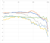
These things occur to me to mention……….
- I did the full tones comparison rather than just the top end for a thorough comparison.
- So, picture of charts attached, the red/brown line is the higher capacitance, blue is the lower capacitance,
- I still see occasional variations like the wee dip at 180 Hz, looking, i think its evident on both plots at slightly different frequencies, maybe a development clue?
- And the readings aren’t very stable at the extremes
- Does the 20,000 fall off happen because of the window limitation, if I can find the setting and if I go 10-30,000 Hz will that change it?
- What is the low end fall off…..?
- I am delighted to now be able to make these comparisons……….
- I am sure there are more rigorous things I can introduce, but it’s a good start for now!
- Is there a convention on vertical scale, obviously i can make this look flat by reducing that, but that's not the point!
- I hope it will enable my developments to progress.
Attachments
So, with Technics 205 cartridge and Jico SAS stylus at 1.3g in my RTA fed to my Rod Elliott P06 phono pre, I plotted the results with three different capacitance levels between the cartridge and phono pre;
1. Short leads only, grey curve, one assumes of negligible capacitance
2. Short leads plus 100pf, blue curve
3. Short leads plus 220pf, red curve
I exaggerated the Y axis to emphasise the differences between them in the chart below.
All show a little inconsistency at 160Hz, this was not apparent in any of the equipment or test validation that helpful friends patiently took me through.
So, i expect that is a result of something in the tonearm/cartridge interface area? - which i would like to seek out and rectify.
There may be additional improvements in the response to be gained with the resistance across the input as well?
I have not yet done much listening but feel the recent changes to the RTA, by minimising the vertical lever, close proximity of the phono pre, these capacitance experiments and general tidying up have been worthwhile!
- Home
- Source & Line
- Analogue Source
- DIY linear tonearm