Listened to a few discs now, it plays music somewhat as before but is perhaps "uninteresting"
First i notice the bass remains open and full, resonant when it should be but not boomy.........
The treble, i hear cymbals and brush/snare drum effects very open.
I hear good detail, a voice in the background of a recording i never heard before, separation of instruments etc.
Maybe the mid is sucked out?
Is there a way i can measure the frequency response out put of the phono-pre, using the same test record and VA set up?
I can measure room response using REW, and possibly compare with previous from years ago, but perhaps not the same thing?
M
@Mike56 the appearance of the mid being sucked out could be cartridge loading. If the highs are pronounced this would account for the mids.
The easiest way to change cartridge loading is to use external loading plugs. For my MC input I have no load R or C and use external RCA plugs with the load soldered across the plug. This way it's easy to swap loading. I use an RCA Tee.
Correct loading even for an MM is important for high fidelity playback. Very low capacitance is not necessarily a good thing as the load is designed to flatten the frequency response. Those who significantly alter the load from the manufacturers recommended are most likely compensating for other deficiencies in their system, or even personal tastes.
The load C specified by the manufacturer is a good place to start and some experimentation may needed to dial it in for your system. I use Pink noise into a spectrum analyser with an inverse Pink Noise filter. If you don't use the inverse filter the the Pink Noise will tilt downwards to 20kHz at 3dB/oct. You can set this filter up in VA, but it needs to be done manually.
I would not measure room response as it's not necessarily what's coming off the TT, if you have the mic in a slightly different spot the result could be completely different. I would start by measuring the TT.
Another fine mess i got myself in Warren..........
Hopefully i can extricate easily, i left the inside wiring of my PO6 in place so could revert to the external input wiring at the phono T.
I foresee a number of possible ways and know you will have already sorted a suitable one, do you please have a pic or diagram of the phono T application?
As I see it i can then somehow wire delicate cartridge input wires to a RCA plug, insert that in the phono T in line and plug that in the input, using the T to insert a capacitor loaded plug or a switched load board. all that on each channel
All unshielded, any problem?
Could get a new box and leave space for a switched input loading board inside............
M
This is the RCA Tee I use
https://www.jaycar.com.au/rca-gold-...1324bd7ba5ecec51ef2614952cc634&sort=relevance
You could also wire a set of RCA plugs in parallel.
https://www.jaycar.com.au/rca-gold-...1324bd7ba5ecec51ef2614952cc634&sort=relevance
You could also wire a set of RCA plugs in parallel.
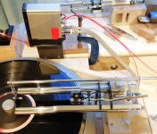
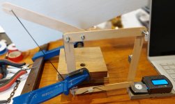
For some of you who may not have enough to do, please have a look below at my latest iteration.
It has a new lighter carriage, carbon crossmembers and lighter rear carriage rail, shortened also to remove unnecessary rail length.
It is now playing with the cartridge wires directly into my phono pre, neatly taped to its stand!
I always admire other posters construction standards!
It played its first side while i typed this up, all went well.
Auto suggestion kicks in here and tells me it sounds better.
Anything that takes a few days to make must sound better, mustn't it?
Sether may notice this has allowed removal of the front ballast weight, because of the lighter back end.
Horizontal and total mass are over 5gms lighter.
I cannot pretend i expected an audible difference, but very clean bass lines and tunefulness, clear top end are noticeable to me.
I will do some measurements at some point.
This will also allow me (eventually!) to lower the CW arm which will remove a small rising VTF in warp, a couple of 10ths in 5mm of warp, totally irrelevant (imho) in real life but i will do it anyway!
M
Attachments

This will also allow me (eventually!) to lower the CW arm which will remove a small rising VTF in warp, a couple of 10ths in 5mm of warp, totally irrelevant (imho) in real life but i will do it anyway!
M
Mike be careful altering the COG from where it is, a few 10ths of VTF increase in 5mm means the COG is slightly under the virtual pivot. If you raise COG too far and have VTF going low as the stylus rides up then it means the COG is above the virtual pivot, this will destabilize the cartridge.
Thanks Warren,
Prompted me to think more clearly.
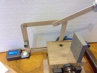
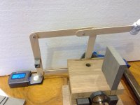
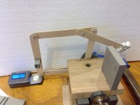
In my arrangement (i believe!) it behaves as shown below by my large scale mock up, and is a result of the lever behaviour on the paralelogram. 10mm warp modelled at around 5 X scale!
What I should have said was;
In warp, with my current construction, as the cartridge rises 5mm the VTF reduces a few tenths. As the cartridge never does that much in real life it may be irrelevant!
However:
Raise the CW lever above horizontal and VTF lowers with rising warp
Lower the CW lever below horizontal and VTF rises with rising warp
Flat lever and it all stays the same………
So I shall aim for the flat lever at some iteration of construction.
Other things may be going on as well, but this is what I am focussing on just now!
M
BTW, I feel if it were a simple lever PTA and the lower part of the paralelogram didn’t exist the same thing would be happening…….
Prompted me to think more clearly.
In my arrangement (i believe!) it behaves as shown below by my large scale mock up, and is a result of the lever behaviour on the paralelogram. 10mm warp modelled at around 5 X scale!
What I should have said was;
In warp, with my current construction, as the cartridge rises 5mm the VTF reduces a few tenths. As the cartridge never does that much in real life it may be irrelevant!
However:
Raise the CW lever above horizontal and VTF lowers with rising warp
Lower the CW lever below horizontal and VTF rises with rising warp
Flat lever and it all stays the same………
So I shall aim for the flat lever at some iteration of construction.
Other things may be going on as well, but this is what I am focussing on just now!
M
BTW, I feel if it were a simple lever PTA and the lower part of the paralelogram didn’t exist the same thing would be happening…….
Attachments
-
 WIN_20240208_09_08_10_Pro.jpg428.9 KB · Views: 60
 -
 WIN_20240208_09_07_55_Pro.jpg437.4 KB · Views: 58
 -
 WIN_20240208_09_07_28_Pro.jpg389.1 KB · Views: 57
 -
 WIN_20240208_09_07_01_Pro.jpg432.1 KB · Views: 56
 -
 WIN_20240208_09_06_48_Pro.jpg426.9 KB · Views: 61
 -
 WIN_20240208_09_06_33_Pro.jpg434.3 KB · Views: 62
I like the Tee or similar F and so on, is there a clever way to wire the tiny cartridge leads into the RCA plug that you are aware of?This is the RCA Tee I use
https://www.jaycar.com.au/rca-gold-...1324bd7ba5ecec51ef2614952cc634&sort=relevance
You could also wire a set of RCA plugs in parallel.
M
What I should have said was;
In warp, with my current construction, as the cartridge rises 5mm the VTF reduces a few tenths. As the cartridge never does that much in real life it may be irrelevant!
However:
Raise the CW lever above horizontal and VTF lowers with rising warp
Lower the CW lever below horizontal and VTF rises with rising warp
What I would aim for is a balanced parallelogram. What I mean is that when it's balanced so it floats there should be NO seesaw affect, the cartridge should stay anywhere it's put in the vertical plane.
This increases stability of the cartridge platform and reduces warp induced shake of the stylus.
Last edited:
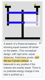
#5309 - great job, Mike: that mockup provides very clear results in a simple and direct way.
It is a topic that has already been partly discussed long ago, starting with #2384 # 3019 mockups, and during all the Lil Casey MK1,2,3 RTA projects - But to spare that trouble I believe that just a look at the usual Wikipedia may be helpful to clear some doubts.
https://en.wikipedia.org/wiki/Roberval_balance + attachment
The main point to note is - and the top 3 points colinear - while removing what is in the white box does not change the situation at all (= letter balance ).
ciao - carlo
have you ever tried a spring CW? i made an attempt on LC1 (on Walter advice), with some issues due to string friction, but in theory it works flawlessly (do you remember the LUXO lamps?)
Attachments
Warren and Carlo, the co-linear top line will achieve the balanced result, this only escaped me this time because some other geometrical confusion intervened. It is all quite small now and difficult (for me!) to foresee all eventualities, so i solve them after falling over.
I will re-make that part over the coming days.
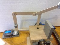
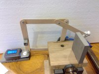
And Carlo, interestingly the changing force from a spring in extension might be used to balance the non linearity of the a non-colinear top line........
Any idea what this old donkey is talking about? - i rarely know myself......!
I will try to set up my mock up to demonstrate!
Here it is in the picture attached, the chord on the left is elastic thread, there is now no CW! - as the stylus rises the spring extension is reduced and so its force but its mechanical advantage on its lever increases and by trial and error i can tell you this device stays within a few hundredths of constant vtf over a 10mm warp height.
Is that of any use to anyone?
I don't know, i shall continue to use my long lever counterweight solution that i have used for some years. Currently the CW is 2.5gms.
I started using it when doing tracking experiments early on the lighter weight on a longer lever tracked better.
M
I will re-make that part over the coming days.
And Carlo, interestingly the changing force from a spring in extension might be used to balance the non linearity of the a non-colinear top line........
Any idea what this old donkey is talking about? - i rarely know myself......!
I will try to set up my mock up to demonstrate!
Here it is in the picture attached, the chord on the left is elastic thread, there is now no CW! - as the stylus rises the spring extension is reduced and so its force but its mechanical advantage on its lever increases and by trial and error i can tell you this device stays within a few hundredths of constant vtf over a 10mm warp height.
Is that of any use to anyone?
I don't know, i shall continue to use my long lever counterweight solution that i have used for some years. Currently the CW is 2.5gms.
I started using it when doing tracking experiments early on the lighter weight on a longer lever tracked better.
M
Attachments
I guess the rain is atrocious with you as well, not days for outside at all!
The spring balanced, no CW radial is probably going to stay in the mind only at least until i have exhausted other thoughts!
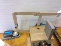
The idea lends itself readily to the paralelogram and lever arrangement I have and the crude mock-up behaves remarkably consistently.........I was surprised, 5 minutes of moving the lever angle around and it was showing consistent VTF over 10mm of height movement.
M
The spring balanced, no CW radial is probably going to stay in the mind only at least until i have exhausted other thoughts!
The idea lends itself readily to the paralelogram and lever arrangement I have and the crude mock-up behaves remarkably consistently.........I was surprised, 5 minutes of moving the lever angle around and it was showing consistent VTF over 10mm of height movement.
M
I guess the rain is atrocious with you as well, not days for outside at all!
The spring balanced, no CW radial is probably going to stay in the mind only at least until i have exhausted other thoughts!
The idea lends itself readily to the paralelogram and lever arrangement I have and the crude mock-up behaves remarkably consistently.........I was surprised, 5 minutes of moving the lever angle around and it was showing consistent VTF over 10mm of height movement.
M
Mike I would suggest you listen to the spring balanced LTA with a stethoscope to ensure you have no spring noise. When I was building mine someone suggested I use springs on the VTA adjusters and these audibly rang when I put a stethoscope anywhere on the structure including the rail.
I thought I'd play with cartridge loading and here are a couple of plots of a Grado Opus 3 modified with a Boron CL and Microridge diamond.
This is a plot of pink noise from the Ultimate Analog test LP so the plot is not flat because it's raw with the 3dB/oct fall. You can clearly see the resonant peak in the last plot where I added a 0.1uf cap to that channel and the difference between 22k and 47k loading.
I need to investigate this a little further because it doesn't look like the frequency response is flat.
- Home
- Source & Line
- Analogue Source
- DIY linear tonearm