I have started mounting my tungsten rings on titanium wheels.The polish of the rings is exceptional but i can feel ripples in the outside surface.
The outside diameter of the two rings also varies by about 0.25mm.
I am going to have to regrind form/polish the outside of them.
I suppose they were only sold as decorative items so cannot expect precision!
I will get some pictures up soon,ive been reading all the fascinating posts recently.
That's disappointing............ I bought 2mm polished carbide rings off eBay and they measure concentric and are consistent between the 2 rings.
Hi Niffy, I would like your opinion about the sine bar test procedure, because what I saw and measured really surprised me. Now, seeing the difference caused by 1/10 shim, the difficulty of leveling the Lil Casey (the bubble level was completely inadequate) becomes clear.
This behavior is different from the reverse pendulum: in the pendulum we move the fulcrum until the stiction reaches the break point, the carriage starts and decelerates until stopping. I remember your bell curves that perfectly described the phenomenon. In the first part of the race, however, the pendulum accompanies the carriage: so the curve describes more the movement of the carriage or that of the pendulum?
sine bar test procedure
stiction
(A) - using thicker shims until finding the stiction break point - start of motion - this provided measures as variable as with the pendulum
(B) - using ever thinner shims up to find the stiction - motion stop - this strangely provided much less variable measures
C - remembering what happens on the eccentricities at the turning point, to reproduce the situation was used the shim that just caused the motion, and a little push uphill: the carriage slows down, stops and - surprise - goes back. You have to decrease the shim by at least 10-15 tenths to find the limit stiction (no backward motion). this strangely gives consistent measures
friction
(A )- using the stiction shim (even the C one) there is a uniformly accelerated motion, because the friction is always much lower
B - the motion is started with the least possible energy (with the cable tie of my cat whisker test) and the shim is progressively reduced until an almost uniform motion is observed - if the carriage does not reach the rail's end the shim is too little, if it goes to smash too big. Seems very critical, but in practice the forces balance can be clearly seen (a 0.05 shim difference is enough)
carlo
Dahlberg - I really like your last graph (cutter wheel) but don't understand the position the CW, so far from the pivot: needing to increase the effective vertical mass?
base rotation: on the Lil Casey mk1 was used a spring+conical pin that enters a hole (as on the indexing wheels), on the mk2 whith a square base a simple stop works fine
Last edited:
The drawing of the "Olfa rotary cutter" solution is for now just a scetch to describe the idea.
If built as in the drawing the whole thing would weigh in at ~8,2g using a 70/75 aluminum
alloy for the supporting structure. It schould be possible to reduce that to maybe 2/3.
The outside diameter of the cutter is not changed from 28mm (smalest size available).
Pivot 1,5g
Pivot holding section 0,9g
Larger diameter section 4,8g
Cutter 1,3g
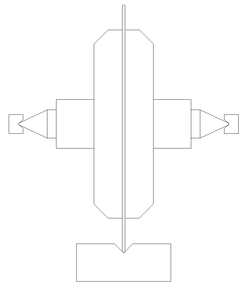
Edit: Apparently there are 18mm cutters as well.
If built as in the drawing the whole thing would weigh in at ~8,2g using a 70/75 aluminum
alloy for the supporting structure. It schould be possible to reduce that to maybe 2/3.
The outside diameter of the cutter is not changed from 28mm (smalest size available).
Pivot 1,5g
Pivot holding section 0,9g
Larger diameter section 4,8g
Cutter 1,3g
Edit: Apparently there are 18mm cutters as well.
Last edited:
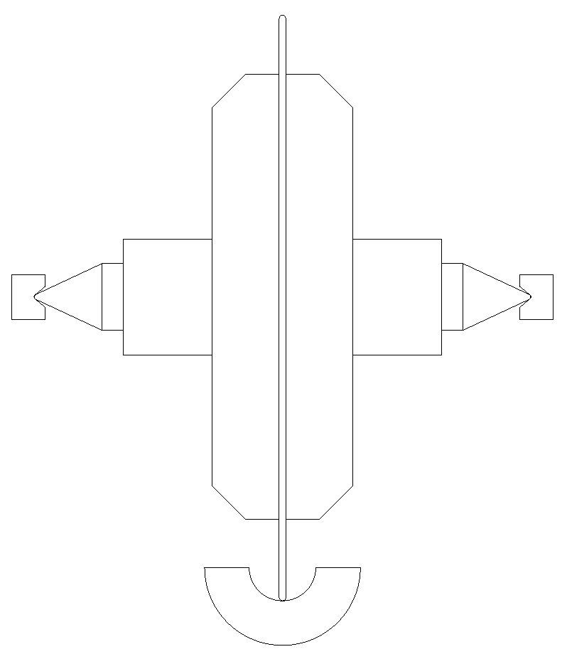
I love that idea too. A rotary knife-edge bearingThe drawing of the "Olfa rotary cutter" solution is for now just a scetch to describe the idea.
If built as in the drawing the whole thing would weigh in at ~8,2g using a 70/75 aluminum
alloy for the supporting structure. It schould be possible to reduce that to maybe 2/3.
The outside diameter of the cutter is not changed from 28mm (smalest size available).
Pivot 1,5g
Pivot holding section 0,9g
Larger diameter section 4,8g
Cutter 1,3g

Maybe the Vee could be replaced by very small diameter Tungsten carbid rods. That would be easier.
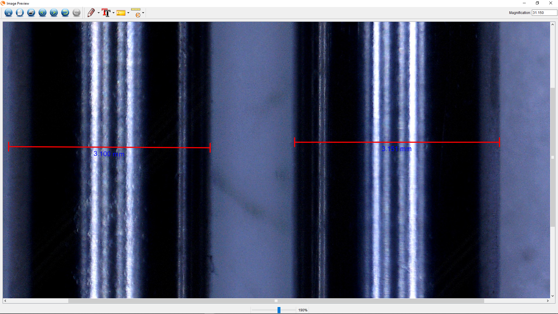
To the left there is a 3,1mm drill that's ment to do the hole for the pivots. They
seem to be 3,15mm (to the right). Does anyone have the experience if I should
even try to pressfit that ? A combination of heat/freeze and pressfit maybe
http://www.dahlbergaudiodesign.se/images/linear_25.png
seem to be 3,15mm (to the right). Does anyone have the experience if I should
even try to pressfit that ? A combination of heat/freeze and pressfit maybe
http://www.dahlbergaudiodesign.se/images/linear_25.png
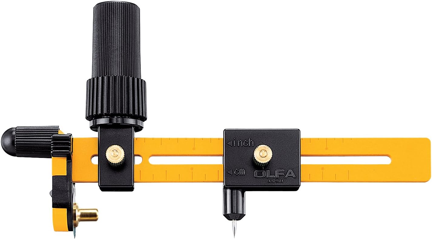
The points in the OLFA Rotary Circle Cutter might come in handy also.
What points, do you mean the lines ?
An externally hosted image should be here but it was not working when we last tested it.

Hi Carlo,
Your sine bar methodology looks fine. A refinement I would suggest is to have one end of the rail resting on a fixed pivot and the other on a pivot attached to a micrometer.
Using a spirit level level the rail by adjusting the micrometer. It doesn't matter what the micrometer is reading at this point but take a note so you can reset the rig easily. Slowly wind in the micrometer until the carriage moves. Record what the micrometer is reading. Reset and repeat multiple times so that you can obtain an average and have more information to analyse. Now repeat winding out the micrometer until the carriage moves in the opposite direction. Again take multiple readings. You can now take an overall average which will tell you where actual level is on the micrometer. The difference between the newly discovered level and the points where the carriage started moving will give the angle from which the coefficient of static friction can be calculated.
Now set the micrometer to level and advance in small steps until the carriage moves smoothly after being nudged with your "cats whisker" to determine dynamic friction.
So basically the same method as you are currently using but with greater repeatability and more accurate determination of the level point. I would say that this is a better method than my reverse pendulum technique as it gives both static and dynamic friction. Good work.
Niffy
Thanks Niffy - the micrometer was what I originally thought. But instead of buying a depth micrometer, that I have not, I'm thinking of cannibalizing that of the router, that seems quite precise. Now i'm thinking that with such small angles we don't need a real sine-bar, since chords are practically equal to the sinus (as physicists do, so why not, simplifying greatly the design). The problem remain the initial set up, even a good bubble level is completely insufficient - maybe my laser one, measuring it's projection on the wall, may work.
The idea of measuring the stiction from the stop uphill does convince you??
...3,15 inside 3,1 .... Does anyone have the experience if I should even try to pressfit that ? A combination of heat/freeze and pressfit maybe.
Hi Dahlberg - since no one answers, i'll try, even being the least qualified to talk about microns
- first question: the coupling is tungsten carbide - aluminum? aluminum is soft, but sticking. Pressing a too tight coupling broachee the hole.worsening the situation.
- second question - 3.1 - 3.15 are strange measures, but are they metric? seems a axle for a 1/8 " bushing
- third question - the 3,1 is a drill bit or a reamer? because a drill bit of 3,0 in aluminum never makes a hole of 3,0 (since is almost never a tip made for aluminum).
About prescripted tolerances there are around all the tables you want and you know. Good for production, less for diyers. For me 5/100 seems too big even for a ten times diameter. I simply trust on practice: leaving 1/10 of flesh and then starting the usual go-no-go procedure with the upper slide at 5°. Stopping just before it's too late, is the ancient recipe.
With the aluminum my last step is a very light pass with rough abrasive paper (not altering the diam). This creates burrs that the press fit will crush, by limiting a lot the necessary pressure. Sometimes to use some epoxy as a lubricant may help.
Heating works well with bigger diameters, freezing into our - 4° - 6° fridge is more or less useless
in short, we do what we can
carlo
Last edited:
Thanks Carlo.
I tried it with the 3,1mm drill, not even close Got some 3,2mm drills
yesterday that might work better. I got delayed a bit since I realised that I have
to adjust the tailstock of the lathe first. When I'm at it I will give it some more
attention as well. I have decided to give the olfa knifes a go since I already
have them, the tungsten rings seems to be at least a month away so....
YouTube
I tried it with the 3,1mm drill, not even close
Got some 3,2mm drills yesterday that might work better. I got delayed a bit since I realised that I have
to adjust the tailstock of the lathe first. When I'm at it I will give it some more
attention as well. I have decided to give the olfa knifes a go since I already
have them, the tungsten rings seems to be at least a month away so....
YouTube
the tailstock is always off center - by definition. but unfortunately so small holes can't be bored.
olfa - maybe even dremel diamond wheels may work. of course taking the diamonds away from circumference with a diamond file.
for the v rail two hss square for tools, glued together. Normally well ground, and finish can be easily improved.
carlo
...this thread is becoming the machinist's corner...
olfa - maybe even dremel diamond wheels may work. of course taking the diamonds away from circumference with a diamond file.
for the v rail two hss square for tools, glued together. Normally well ground, and finish can be easily improved.
carlo
...this thread is becoming the machinist's corner...
Hi Carlo,
You can use a normal caliper type micrometer as long as you can mount it rigidly, such as in a vice. Open up the jaws by about 20mm and use that as your starting point. With the method I am proposing initial leveling of the rail is not required. Neither is zeroing of the micrometer. Take the reading for when the carriage moves to the left and subtract the reading for when it moves to the right. Divide this by 2. Divide this by the length of the rail between the supports and you have your coefficient of friction.
Your uphill measurement might not be as accurate or easy to perform but can definitely be useful as a double check.
Niffy
So here is another idea. An "Olfa rotary cutter blade" gets a radius instead of a sharp edge and a supporting structure. The blade is 0,3mm thick and has a diameter of 28mm and is made from tungsten. Comments anyone
TC is very hard and capable of machining high speed steel so the rail would need to be at least as hard as the wheel, requiring a TC rail. Maybe 2 blades spaced apart by a shim running on a single TC round rod.
Putting a radius on the blade will require diamond tooling.
Thanks Niffy - the micrometer was what I originally thought. But instead of buying a depth micrometer, that I have not, I'm thinking of cannibalizing that of the router, that seems quite precise.
carlo
Hi Carlo,
Micrometer heads are available on eBay for about $15USD. I had one of these as a saddle stop on my previous lathe. You can also get cone instead of flat which is what I used.
AU 0-25mm Metal Thread Micrometer Head Flat Needle Precision Measure Tool | eBay
TC is very hard and capable of machining high speed steel so the rail would need to be at least as hard as the wheel, requiring a TC rail. Maybe 2 blades spaced apart by a shim running on a single TC round rod.
Putting a radius on the blade will require diamond tooling.
So diamond tooling it is, same as with the tungsten drills/pivots
I'm not expecting the blades (with a radius) to make any damage to the 7075-6
aluminum, it's basically hard as steel. The trick would be to create a "V" with a
controled radius and to line up the "wheels"correctly.
You can actually cut the 7075-6 aluminum with a regular handheld router
So at least, a 90 degre "V" is quite simple to create.
- Home
- Source & Line
- Analogue Source
- DIY linear tonearm