Hi Dahlberg,
When I was using my steel on steel bearings I used them with a little bit of petroleum jelly. They seemed to run just a little bit smoother with it although this difference could have been within the error bar of my test rig. To be honest I couldn't hear any difference in sound with or without lubrication.
With ballrace bearings they definitely work better dry. With pin bearings it doesn't make a significant difference, not significant enough to be heard. As Warrjon mentioned, grease will trap dust. When I took the steel bearings off the arm after several months of use the petroleum jelly did look a tad hairy.
I would probably not use lubrication if I were to use steel bearings again.
I run the sapphire tungsten carbide bearings dry.
Niffy
Prototyping looks like this at this moment. Titanium armtube (100x6x4mm),
aluminum carriage and cartridge mounting plate (70/75 alloy, 8mm thick).
Carriage should weigh in at 50-60g incl cartridge and counter weight.
Rods will be polished 6mm H6.
The arm will rotate at the base and there will be some additional functions
added as well.
http://www.dahlbergaudiodesign.se/images/linear_18.png
Hi Dahlberg,
I seem to have missed this post. Looks like a good design. One of my earliest versions of the arm (which I didn't get working) used a rotational base. I do like the idea of rotating the arm away from the record either horizontally or vertically as with the clearaudio. A slide mechanism, as I use, requires an additional structure for the bars that will inevitably have a resonant character. A sliding system is simple and makes the dressing of the arm cables easier. My early prototype never seemed to lock into the same place meaning that the LTA varied. This is more a reflection on my design than on the idea of rotation.
If you are using 2mm wide wheels you will have a contact angle with the rail of over 40°. Ideally I think that the contact angle should be 20-30°. The absolute maximum would be 45° which you should just squeeze under depending on the edge profile of your wheels. Using 3mm wide wheels will reduce the contact angle to 30° but will dramatically increase vertical friction. During my testing period I built a rail and set of wheels that were 3mm wide with a contact angle of about 30°. I actually built this rail expecting it to fail just to see if it would fail as predicted. It did. Vertical friction was too high causing vertical motion to be over-damped leading to a flattened sound. I would recommend using 4mm rods for your rail. I initially used borosilicate glass before moving on to tungsten carbide. A quick scan found this. It is also h6 tolerance.
Metric Silver Steel
Niffy
Hi Dahlberg,
Have you calculated the vertical location of the centre of mass of the carriage Inc cartridge? Ideally it wants to be level with the vertical pivot point which will be a little over a millimetre above the bottom of the wheel (assuming you have 2mm wide wheels and a contact angle of 30°). There is an argument for having the centre of mass slightly lower than the pivot point for stability reasons. It's not clear from the plan you posted what the mass distribution will be. It looks like the centre of mass will be above the pivot.
Another point that Jim raised a while ago is the importance of having a derail preventing mechanism. During normal play back this is not so important but during record changing it is. Jim nearly took out one of his collection of cartridges when he was changing a record on his early mechanical linear arm.
Niffy
Here is a suggestion for the protection mechanism.
Jim
Hi Jim,
Perfect. It doesn't add unnecessary mass to the carriage and also acts as a dust guard for the rail.
Niffy
Here is a suggestion for the protection mechanism.
Jim
Hi Jim,
That works well. I have an acrylic dust cover on my current setup attached to the rail with a channel machined into it for wheel clearance, it also prevents the carriage from de-railing.
carriages, carriages
Hi all, watching at your incredible works I had an attack of "improve-algia"- Having finally found where to buy the square carbon tubes (R&G in Germany) I'm toying on these hypotheses (attachment) for a possible hyper super Lil Casey mk last.
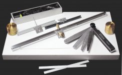
Already made some quick prototypes and some tests with a kind of "sine bar" - simply various thickness-gauge blades put under one rail support to start the motion (stiction), o rto maintain it (friction) - Behaviors* are rather different from those seen with the inverse pendulum.
A solution - Total weight = 16 gr
friction - runs with a tilt of a 0,35 shim / 300mm rail. angle=0°4'1" = 0,067 decimal --- μ=0.0012
stiction - starts with a tilt of a 0,75 shim / 300mm rail. angle=0°8'36" = 0,143 decimal --- μ=0.0025
B solution - Total weight = 14 gr
friction - runs with a tilt of a 0,70 shim / 300mm rail. angle=0°8'1" = 0,141 decimal --- μ = 0.0024
stiction - starts with a tilt of a 1,10 shim / 300mm rail. angle=0°12'36" = 0,200 decimal --- μ = 0.0035
C solution - Total weight = 12 gr
friction - runs with a tilt of a 0,25 shim / 300mm rail. angle=0°2'52" = 0,047 decimal --- μ = 0.0008
stiction - starts with a tilt of a 0,65 shim / 300mm rail. angle=0°7'27" = 0,124 decimal --- μ = 0.0022
after all, not so bad for such common means, and a 5000 years old tech. The A solution is quite similar to the mk2, the B instead completely disappointing, the C may be the right one, even if difficult to make properly with my tools (better, without some tools)
carlo
*the measures are an average, obtained alternating the shims under the left and right support, to compensate for any deficiencies in the leveling of the base.
sine bar angles - calc
Sine Bar & Sine Vise Calculator - LittleMachineShop.com
angles - degrees to decimal - calc
Degrees,minutes,seconds to decimal degrees converter
Hi all, watching at your incredible works I had an attack of "improve-algia"- Having finally found where to buy the square carbon tubes (R&G in Germany) I'm toying on these hypotheses (attachment) for a possible hyper super Lil Casey mk last.
Already made some quick prototypes and some tests with a kind of "sine bar" - simply various thickness-gauge blades put under one rail support to start the motion (stiction), o rto maintain it (friction) - Behaviors* are rather different from those seen with the inverse pendulum.
A solution - Total weight = 16 gr
friction - runs with a tilt of a 0,35 shim / 300mm rail. angle=0°4'1" = 0,067 decimal --- μ=0.0012
stiction - starts with a tilt of a 0,75 shim / 300mm rail. angle=0°8'36" = 0,143 decimal --- μ=0.0025
B solution - Total weight = 14 gr
friction - runs with a tilt of a 0,70 shim / 300mm rail. angle=0°8'1" = 0,141 decimal --- μ = 0.0024
stiction - starts with a tilt of a 1,10 shim / 300mm rail. angle=0°12'36" = 0,200 decimal --- μ = 0.0035
C solution - Total weight = 12 gr
friction - runs with a tilt of a 0,25 shim / 300mm rail. angle=0°2'52" = 0,047 decimal --- μ = 0.0008
stiction - starts with a tilt of a 0,65 shim / 300mm rail. angle=0°7'27" = 0,124 decimal --- μ = 0.0022
after all, not so bad for such common means, and a 5000 years old tech. The A solution is quite similar to the mk2, the B instead completely disappointing, the C may be the right one, even if difficult to make properly with my tools (better, without some tools)
carlo
*the measures are an average, obtained alternating the shims under the left and right support, to compensate for any deficiencies in the leveling of the base.
sine bar angles - calc
Sine Bar & Sine Vise Calculator - LittleMachineShop.com
angles - degrees to decimal - calc
Degrees,minutes,seconds to decimal degrees converter
Attachments
Last edited:
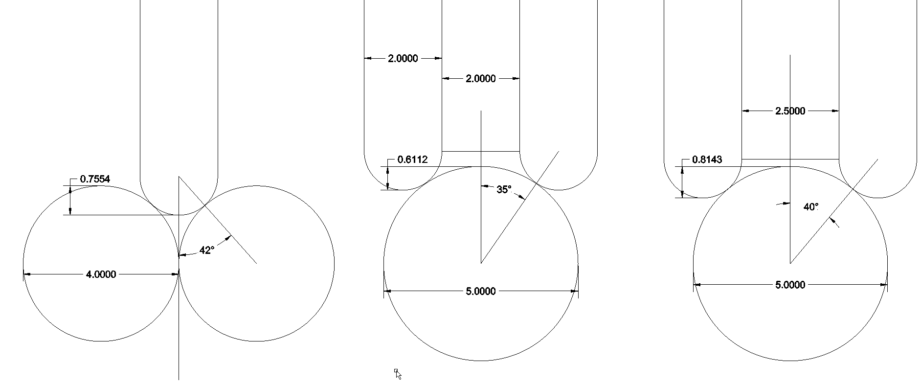
So here are some alternative solutions with material that I actually have or have ordered (the rings haven't arrived yet). I only have one 5mm rod.
From left to right:
1: Dual rings and 6mm rods. Hight difference rings/rods 0,53mm.
2: One ring dual 6mm rods. Hight difference rings/rods 1,3mm.
3: Same but rods 1mm appart. Hight difference rings/rods 2mm.
4: Dual rings rods 1mm appart. Hight difference rings/rods 0,86mm.
5: 5mm rod dual rings 2mm appart. Hight difference rings/rods 0,6mm.
6: 5mm rod dual rings 2,5mm appart. Hight difference rings/rods 0,8mm.
http://www.dahlbergaudiodesign.se/images/linear_19.png
Hi Carlo,
It's great to see some further developments.
The sine bar looks like is works really well giving both static and dynamic coefficients of friction.
Option C really does tick all the boxes. The coefficient of static friction you have achieved is only slightly greater than I achieved with my full exotic materials solution. However your carriage mass is less than a quarter of mine. The actual force that will need to be applied at the stylus to get the carriage moving will be only 27% of what is required for my arm. A stunning result.
Option C also has the advantage that it should be much more stable. What are you using for the square section with the corners cut out?
Niffy
Hi Dahlberg,
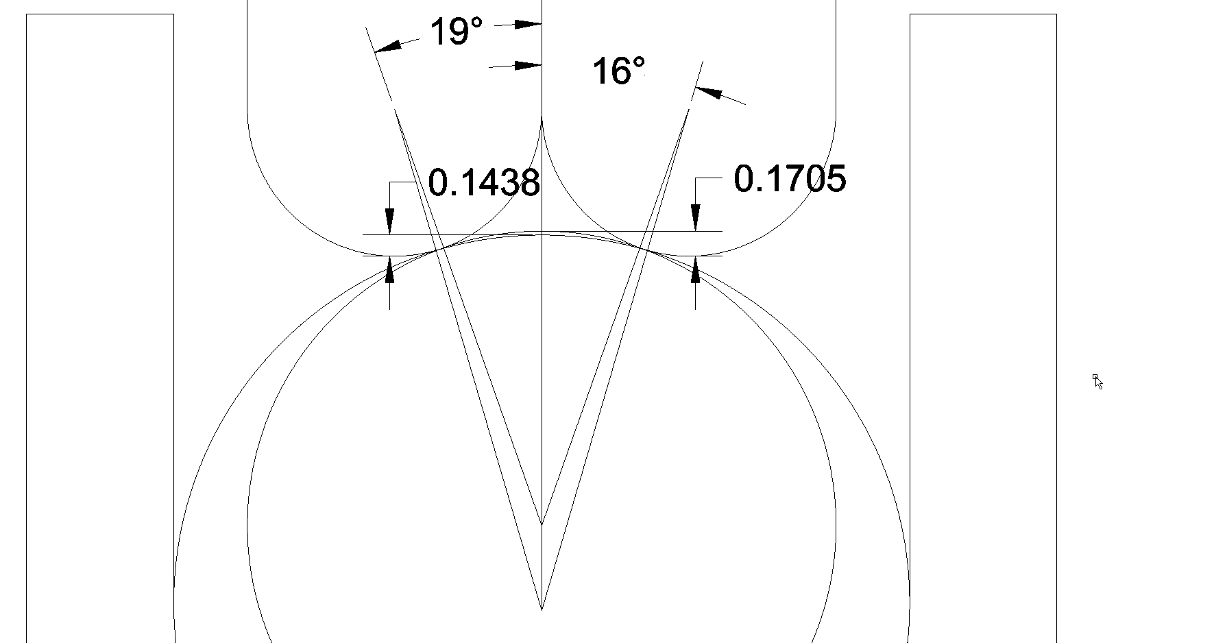
One of the disadvantage of making the wheels with double rings is that it will both increase mass and raise the centre of mass of the carriage. If you are using just a single rod for a rail and double dome edge rings I would recommend still going for the smaller diameter rod if possible. Don't bother with a spacer between the rings. With a 5mm rod the contact angle will be 16.6° which is fine as long as your derail prevention is good. With a 4mm rod the contact angle will be 19.5° which is perfect.
Another thing with the double ring system is that it could result in greater friction in the vertical plane. The friction will be proportional to the distance the rings have to slide over the rail. The 5mm rod will result in 25% more friction than the 4mm. The 4mm rod with the dome edge rings will give about the same vertical friction that I have with my arm.
If you are using a dual rod rail and a single ring wheel you can use either a dome edge ring or a plain edge ring. 4mm rods and 2mm dome edge rings will give a much greater contact angle than with the plain edge. The plain edge ring will give greater vertical friction. I tried both edge profiles and preferred the sound of the plain edge wheels. I think that this is due to three factors. The smaller edge radius will result in a smaller contact point which should improve coupling/mechanical grounding. The lower contact angle will result in smoother lateral motion. The higher vertical friction will damp the vertical motion of the arm more.
I've tried set ups with both higher and lower levels of vertical friction/damping than I am using at the moment. I think the level I am currently using is optimal for my cartridge.
Niffy
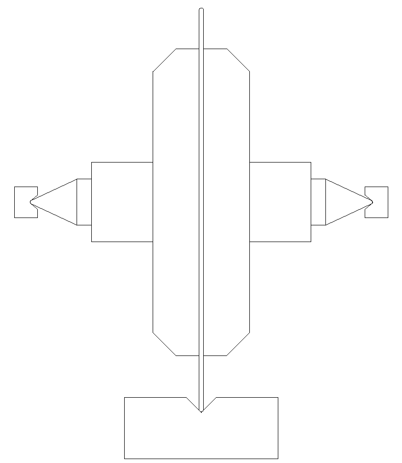
Well I haven't recived the rings yet so for now I'm drawing them as radius 1mm (not correct but...).
I found the angles you mentioned Good derailing system less than 0,2mm of margin 
and that's with rings as 1mm radius. From the picture it will be less.
http://www.dahlbergaudiodesign.se/images/linear_22.png
I found the angles you mentioned
Good derailing system less than 0,2mm of margin and that's with rings as 1mm radius. From the picture it will be less.
http://www.dahlbergaudiodesign.se/images/linear_22.png
If I draw a line from the outside corners it looks promising but I'm not sure that's
the acurate way to do it. The cartridge and counterweight stand for a
substantial amount of the combined mass.
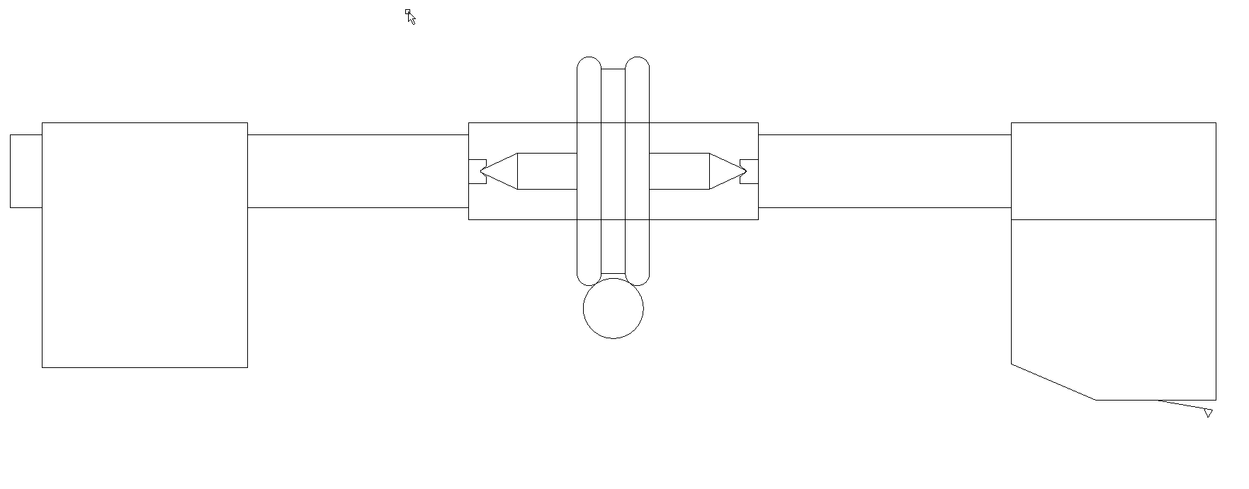
http://www.dahlbergaudiodesign.se/images/linear_21.png
the acurate way to do it. The cartridge and counterweight stand for a
substantial amount of the combined mass.
http://www.dahlbergaudiodesign.se/images/linear_21.png
Hi Niffty, as you may remember the only problem left open in the LC mk2 is the possible carriage tilting: in practice, with an accurate set up for the chosen VTF it does not occur, but knowing that it could happen somehow bothers me.
As someone says: never fix what's not wrong. Given the significant improvement from mk1 to mk2, I am determined not to increase the vertical effective masses in any way. No double rails, no heavier carriage: not an easy path to explore.
Solution A does not change really the situation, it's just a little more sliding and self-centering, perhaps due to a more linear path of the spheres, but not enough to justify a new construction.
I expected that the solution B. with only two larger balls would be much better, instead it has much more stiction and also the self-centering effect is less, while i hoped that the lateral friction on that diameter could be much greater.
The C seems the only way, but this bakelite version lets just generic evaluations. It is clear that > play = < friction but also > chattering, so everything must to be done with strict tolerances and carefully tuned on the final carbon profile. Provided I decide to try to face the new construction.
The realization is done with a small circular saw that I had built long time ago. Very precise because it has an adjustable screw register, but certainly not a milling machine.
carlo
the "sine bar" allows to accurately evaluate the motion behavior, including friction, even in this rough version, but results must be further checked for a more reliable average - Anyhow, it might be worth building a more serious and comfortable set up.
Last edited:
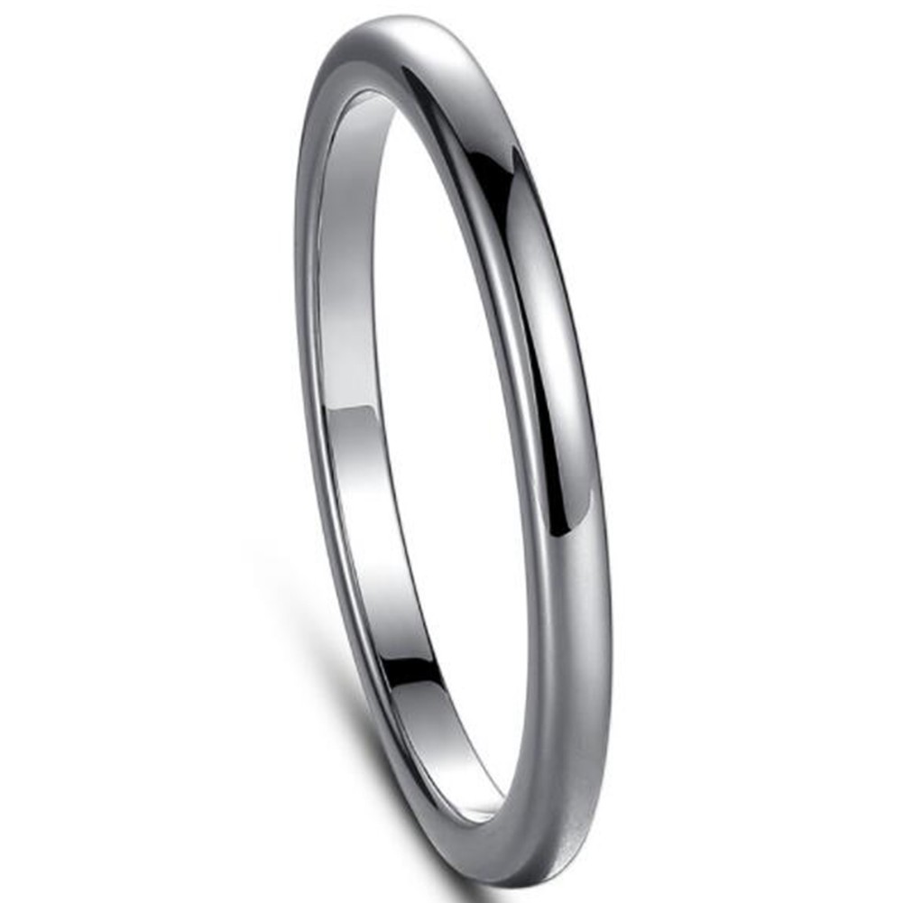
I have started mounting my tungsten rings on titanium wheels.The polish of the rings is exceptional but i can feel ripples in the outside surface.
The outside diameter of the two rings also varies by about 0.25mm.
I am going to have to regrind form/polish the outside of them.
I suppose they were only sold as decorative items so cannot expect precision!
I will get some pictures up soon,ive been reading all the fascinating posts recently.
The outside diameter of the two rings also varies by about 0.25mm.
I am going to have to regrind form/polish the outside of them.
I suppose they were only sold as decorative items so cannot expect precision!
I will get some pictures up soon,ive been reading all the fascinating posts recently.
If I draw a line from the outside corners it looks promising but I'm not sure that's
the acurate way to do it. The cartridge and counterweight stand for a
substantial amount of the combined mass.
http://www.dahlbergaudiodesign.se/images/linear_21.png
With the wheel design shown I the diagram the vertical pivot will be at the centre of the single rod. To work out where the centre of mass is located first draw a horizontal line through the centre of the rod. For each component measure the distance from this line to the centre of the component. Things above the line will have a positive value, things below negative. Multiply this distance by the mass of the component. Do this for each component then add all the results together. Divide this total by the total mass. This will tell you where the centre of mass is relative to the vertical pivot.
Hope this helps.
Niffy
I have started mounting my tungsten rings on titanium wheels.The polish of the rings is exceptional but i can feel ripples in the outside surface.
The outside diameter of the two rings also varies by about 0.25mm.
I am going to have to regrind form/polish the outside of them.
I suppose they were only sold as decorative items so cannot expect precision!
I will get some pictures up soon,ive been reading all the fascinating posts recently.
That's disappointing. The rings I purchased were near perfect. They have a very smooth surface and are circular to within 10um and varied from each other by less than about 20um (from memory) . When you say the two rings vary by 0.25mm do you mean that the rings are a different size to each other or do you mean that they are not perfectly circular with the major axis being 0.25mm greater than the minor?
I'm starting to think that I might have been very lucky with the sourcing of my components. A lot of you guys seem to be having inordinate troubles finding quality (and affordable) parts. I hope you find a good solution.
Niffy
- Home
- Source & Line
- Analogue Source
- DIY linear tonearm