A journey in design
Hi Jim,
It looks like we're in pretty much total agreement on all points.
If I may I would like to expand on my assertion that the main benefit of linear tracking tonearms is the ability to utilize short arm tubes, and also on some of the other advantages of linear arms.
Of course the reduction in lateral tracking error is of great importance. Optimal alignment of the stylus with the groove is a must for optimal replay. The removal of the need for an anti-skate device has got to help massively also. Even the best anti-skate device is a shot in the dark at best. The required anti-skate setting varies constantly depending upon both the instantaneous modulation of the groove and the position of the arm over the record. Whether you're playing a 33 1/3 or a 45rpm will change the skating force required dramatically. Another advantage is symmetry. The cantilever, cartridge, headshell and arm tubes are all aligned. The way energy flows from the cartridge into the arm is the same with both left and right movement (note, I am talking about vibrational energy across the audio bandwidth and not about tracking left and right). With an offset headshell this is not the case. Although your fixed air bearing design linear tracking arm is not entirely symmetrical the headshell is as is the attachment to the sliding bar. This will make it behave very much like it were fully symmetrical.
On to why I think that the short arm is the main reason why these arms sound so good. And to do that I have to take you on a journey.
About 20 years ago I upgraded my tonearm. I had what was a very highly regarded budget arm and replaced it with an equally highly regarded mid/high end arm. I will call them budget arm and high end arm. (I won't say what they were as I want to avoid getting bogged down in discussions of their individual merits). The high end arm cost about 6 times as much as the budget arm. Both were 9" with similar geometries. It was a very successful upgrade. Two things were very apparent.
First.
The high end arm sounded a lot better in every way. Think of a hi-fi speak to describe sound quality and the high end arm did it better
Second (and more importantly)
It sounded better across the whole record. With both arms there was a slight variation in sound quality as the arm tracked, moving into and out of the null points. This variation was slightly more noticeable with the high end arm. BUT the high end arm whilst playing the innermost groove (where it sounded worst) still sounded MUCH better than the budget arm playing at the outer null point (where it sounded best).
To explore this further I performed a little experiment. At the time I was working in a hi-fi retailer and luckily had access to two identical pre run in cartridges. I also had separate arm boards for each arm so I could mount a cartridge in each arm and very quickly swap them. I set the budget arm so that it was perfectly aligned about 5mm into the first track. This meant that the alignment would be almost perfect for the first couple of minutes of any record. I did the same with the high end arm but this time I purposely misaligned the cartridge by about 3°. Other than that both arms were perfectly set up. The high end arm still comfortable beat the budget arm in all aspects of sound quality. Properly ealigning the cartridge in the high end arm improved sound quality but the improvement was smaller than the difference between the well set up budget arm and the poorly set up high end arm had been.
This got me thinking about what caused the high end arm to be so much better than the budget arm. The deck was the same. The cartridge was the same. The records played had been the same. The geometries of the two arms were almost the same as were the effective masses. The budget arm had been rewired with arm wire that was probably better than that used in the high end arm so it wasn't arm wire. Both seemed to have equally smoothly running bearings. The only conclusion had to be in the way the two arms controlled resonance. This would consist of rigidity, damping and resonant frequency of the entire arm with the armtube playing the major roll. There seemed to be little difference in the level of damping of the arm tubes. My rough calculations suggested that the high end arm was about twice as rigid as the budget arm which resulted in the resonant frequency being pushed up by half an octave. If doubling the rigidity can have this much effect what would happen if you made the arm ten times as rigid? What about a hundred or thousand times as rigid? This is where my obsession with tonearm design was born. The best way of improving resonance control and increasing rigidity is by reducing arm length.
So I do think resonance control is the most important aspect of design. A 3° lateral tracking error made less difference than a relatively small change in resonance control.
Of course 0° tracking error combined with excellent resonance control is much better still
Niffy
Can you show us the construction of the air bearing turntable?
Yes, see (in) my "diyAudio" photo gallery:
Some pictures & text ....
Air bearing TT & TA 16" - My Photo Gallery
It's music ... I like it.
Karel
Can you show us the construction of the air bearing turntable?
... and this; my first one air bearing TT:
Lenco-airbearing-16" - Vinyl Engine
It's music ... I like it.
Karel
...Do you have 16 inch radio transcription discs to play on it?
Thanks for the flowers Consty...
... no 16" (cinema) vinyl-disc(-s) in stock .... hélas ....
Karel
Hi Karel,
I've noticed in your pictures that in terms of TT "suspension" you switched from tennis balls to steel spikes.
Indeed it's a kind of PITA to maintain perfect horizontal alignment (required by the air bearing TA) of a TT placed on a more or less soft base. But are spikes better at isolating the TT from external vibrations? Spikes are usually used for speakers (vibrations generators)")
I've noticed in your pictures that in terms of TT "suspension" you switched from tennis balls to steel spikes.
Indeed it's a kind of PITA to maintain perfect horizontal alignment (required by the air bearing TA) of a TT placed on a more or less soft base. But are spikes better at isolating the TT from external vibrations? Spikes are usually used for speakers (vibrations generators)
.... I've noticed in your pictures that in terms of TT "suspension" you switched from tennis balls to steel spikes. ....
Hey Consty.
You have (good sharp) eagle-eyes ....
Chapeau.
Fyi:
1°) In my first air bearing TT I used (used) tennis ball. Very KIS ... & what I have on the shelf .... (& for minute test).
I noticed that Serina tennis-balls attenuate less than tennis-balls from Cleysters..

2°) In my (last) heavy air bearing TT 16" project I used .... three heavy "leek-hook" (from the shelf) ..... very KIS.

Perso, the utility "spikes" is quasi the same for speakers versus TT (in very normal "domestic" applications) ...
Believe me ... its music .... (that's what my WAF like)
Karel
... why idler instead of belt? ....
Ho, it's a very simple tech history ....
I start to transform (step by step) a stock factory Lenco in a ..... "air-bearing-Lenco" & with all the standard components (motor/idler wheel + tuning/platter .... but, without the shaft-bearing) ....
(some tech-ideas are from Vic's-Terminator c.f.r. motormanagement).
In my case & concept air bearing I have no experience between "lenco-idler-air bearing-platter" versus "belt-air-bearing-platter" ....
Sorry for my limited field test air-bearing .... & no arguments pro-contra ...
I suggest: do-it ....
(with my air bearing no "bearing-floor-noise" ... silence .... you can hear the silence)
But, it's music .... I like it.
Karel
Hi Niffy,
I saw where the conclusion came from.
Yes. I missed skating force of a pivot tonearm. Skating is one of worst factor to degrade the sound of pivot arm. Most arms use a small weight to counter skating force. Such device is very questionable. I have not done any experiment to see how this kind of device will degrade the sound, but in my mind, I suspect deeply it can do a lot of damage. This is why I am thinking to replace such device with a high CST silicone fluid trough.
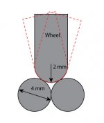
For your arm’s rail, I have a suggestion. Please see the drawing. If the edge of the wheel is 2 mm in radius. Then, even if the wheel swings front and back, its parameter with the rail will not change. And, VTF won’t change either although VTF may not change too much on your existing wheels.
Jim
I saw where the conclusion came from.
Yes. I missed skating force of a pivot tonearm. Skating is one of worst factor to degrade the sound of pivot arm. Most arms use a small weight to counter skating force. Such device is very questionable. I have not done any experiment to see how this kind of device will degrade the sound, but in my mind, I suspect deeply it can do a lot of damage. This is why I am thinking to replace such device with a high CST silicone fluid trough.
For your arm’s rail, I have a suggestion. Please see the drawing. If the edge of the wheel is 2 mm in radius. Then, even if the wheel swings front and back, its parameter with the rail will not change. And, VTF won’t change either although VTF may not change too much on your existing wheels.
Jim
Attachments
Last edited:
Hi Karel,
Thanks for the info!
So, your table actually is an air suspension table. Its bearing is regular bearing. Air Force One has similar construction except their bearing is a true air bearing. The whole platter is part of air bearing and suspended on the air. Your idea is a very clever one. What is air pressure for the table? I have been thinking about air bearing turntable. But I won’t actually do it.
Here is a video from youtube.
https://www.youtube.com/watch?v=sFrVdoOhu1Q
In the beginning of the video, this guy held an air bearing. If this kind of bearing can be use for turntable, I think it is nice, too. The bearing may not need air or use very little compressed air. I am not a mechanist. If anyone has more info on this bearing, please let me know. It is very interesting.
Jim
Hi Niffy,
I saw where the conclusion came from.
Yes. I missed skating force of a pivot tonearm. Skating is one of worst factor to degrade the sound of pivot arm. Most arms use a small weight to counter skating force. Such device is very questionable. I have not done any experiment to see how this kind of device will degrade the sound, but in my mind, I suspect deeply it can do a lot of damage. This is why I am thinking to replace such device with a high CST silicone fluid trough.
For your arm’s rail, I have a suggestion. Please see the drawing. If the edge of the wheel is 2 mm in radius. Then, even if the wheel swings front and back, its parameter with the rail will not change. And, VTF won’t change either although VTF may not change too much on your existing wheels.
Jim
Hi Jim.
There are two disadvantages to the design that you have proposed over the configuration that I am using.
The wheels, in order to keep rolling resistance low, are made from stainless steel. My current wheels are 1.5mm thick. The wheels you are suggesting are 4mm thick. This would increase their mass by about 3.6g per wheel. As all of this extra mass will be above the vertical pivot it will raise the centre of mass above the pivot causing tracking force to decrease when navigating a warp. Also I think keeping the centre of mass level with or slightly below the pivot makes for a more stable arm.
The distance from the vertical pivot point to the contact point in your suggestion is 2mm. In my current design it is only 1mm. This means that to accommodate the same movement, the same warp, the contact point will have to slide twice the distance in your suggestion resulting in twice the vertical friction.
By simply radiusing and polishing the edge of the wheels I achieve a nice smooth contact point and minimum mass.
Hope this answers your query.
Niffy
Hi Jim,
I had to cut the last post short to run an errand.
Another difference between the two designs is that in your design the contact point on the rail is stationary and the wheels slide. In my design the contact point on the wheels moves only a small amount with the major movement of the contact point being sliding on the rail. The amount of movement between the two rods is slightly different with a slightly greater movement on the rear rail. If the angles the arm moves through were large then your design would definitely be better. However as the maximum angle that the arm moves through whilst playing a record is only a fraction of a degree, the difference is not significantly large. The differences described in my previous post outweigh this possible disadvantage.
Niffy
Air Force One has similar construction except their bearing is a true air bearing. ....Your idea is a very clever one.
....What is air pressure for the table?
video from youtube.
https://www.youtube.com/watch?v=sFrVdoOhu1Q
If this kind of bearing can be use for turntable, I think it is nice, too.
Hey Jim.
Thank's for the youtube video link.
Very informatif. (I am a old retired mechanist/safety & engineer)
My air bearing concept is a little different ...
I start my idea in "KIS" (when I saw some air-bearing-TT @ very-high-level & price !?!?!?)
It took me 2 years to study several high-tech-labo-papers "air bearing & applications" ...
In the end, in my case: no exotic machinery & skills ... only the classical machinery ... even @ home ... it's possible (in low cost).
In a nutshell :
1) the upper platter (& glass platter) is lifting up (about appr. 1 ...5 nanometer) and rotate around/in a 3 fine points PTFE (c.f.r bearing Well tempered TT).
It's a quasi absolute centerpoint .... it's still a air bearing (true or not !?!?).
2) The 2 under-platter are the base & air distribution & multiple air nozzels ...
3) For a "lift off" .. I need appr. minimum 1 bar (depend the concept/quantity air nozzles).
Note, a frigo compressor does the job "temporary" (very short time) .... It's not an oil/water free compressor .... a very bad solution (even with filters & cooling).
Perso, my opinion:
I am skeptical about the notion "true air-bearing".
It depends on the mechanical tolerances beween "shaft & hole" or "between two planes" (quality-surface, margin diameters, & diameter irregularities ... ) & stability in time.
I am skeptical about the (nice) application TT "youtubevideoairbearingshaft" special in a long-run-time .... let's test it in vivo, the best way ...
Hé voila some answers @ your musical troubles
Karel
(Jim btw, I follow your air bearing experiences .... chapeau.
For a full air bearing TT ... Do it ... it's a goal)
Last info, I confirm some tech values:
AIR BEARING TURNTABLE 16”
Concept/technical specifications:
Type: air bearing spinning platter
Nozzels: multiple air nozzels (home made)
Dynamic mass: 12kg
Turntable platter: C45 / Dia: 325mmx14,4mm
Motor management: “à la Lenco”, with micro fine tuning Turntable speed (fix): 33,3 RPM
Turntable: 16” Glasplatter 450mmx8mm
Stroboscope : 16” (à la EMT … custom home made )
Center: three points centering (near absolute center)
Air compressor: oil free air compressor
Air pressure turntable: 0,7bar (minimumminimorum)
Total weight: 45kg (appr)
Free run from 33,3 rpm to 0 rpm: total time 11minutes 45 seconds
AIR BEARING LINEAR TRACKING TONE ARM 16”
Concept/technical specifications (home made):
Type: air bearing linear tracker (à la “Terminator”). Effective lenght: 450mm (16”)
Tracking error: 0°
Pressure tone arm air pressure: 0,4bar (appr).
Hey Jim.....How many air nozzles are on the bottom stationary platter?
....How heavy is the top moving platter?
Are you ready to start a "air bearing TT" in home made ....... (?).
Some short answers for your quids:
1) In my last case, I dril (arbitrary) 2x6 pré-holes for the (home made) air-nozzles (in the under platter).
I can easely obture some air-nozzles symmetrical ... (gain in air flow & pressure ..... but some time instability) ...
2) The top platter (even the two under platters ) dynamic weight 12Kg (not included the glass platter).
How many factory "air bearing TT's" (high end & even higher) have a multi air nozzles concept ?
For the fun, my goal was the "lift up" (easily) 100kg & even much more ....(there is a "hydrostatic TT", a real beast, in Germany)
Have a good start ....
Do it ....
The best.
Karel
Dears,
Have you seen this?
https://www.youtube.com/watch?v=zShBDdd-R20
It's a pretty interesting Cantus variation due to both the arm articulation and the double counter weight idea!
Have you seen this?
https://www.youtube.com/watch?v=zShBDdd-R20
It's a pretty interesting Cantus variation due to both the arm articulation and the double counter weight idea!
Attachments
Hi Karel,
I checked Tech Das web site and realized that their Air Force 1 is not a true air bearing table either. Their bearing is a regular bearing with platter floating on the compressed air. It is almost same as yours.
Let me explain what I meant by true air bearing.
Please check this web site first.
OAV Air Bearings
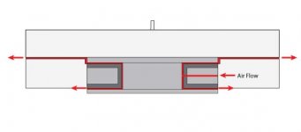
I think of using their 3” ID roller air bearing. It may not be cheap though. Please see the drawing. In this way, the platter is floating on the air and bearing is air bearing, too. This is what I call true air bearing.
Sorry for off the topic.
Jim
I checked Tech Das web site and realized that their Air Force 1 is not a true air bearing table either. Their bearing is a regular bearing with platter floating on the compressed air. It is almost same as yours.
Let me explain what I meant by true air bearing.
Please check this web site first.
OAV Air Bearings
I think of using their 3” ID roller air bearing. It may not be cheap though. Please see the drawing. In this way, the platter is floating on the air and bearing is air bearing, too. This is what I call true air bearing.
Sorry for off the topic.
Jim
Attachments
Hey Jim.
I agree with you, we are "out of topic" (but not our tangential TA) ...
Sorry for our "dérapage" .....
In fine:
You are right about the definition "trough air bearing", I agree.
OAV, I know. Very up-to-date, not cheap for a (full) DIY (in homemade) ... but high class, & a bit complex, & relative higher pressure .....
I like my concept ...KIS ... a full learning project (with pro & contra) ...
Btw, cost: ... for an "apple & egg" .... & competitive with high-class-air-bearing-TT.
I suggest we close or "air bearing TT" ....
Jim, do it (your air bearing TT).
Sorry folks.
Allez, salukes.
Karel
I am following with interest this post...and the link posted by Jim on the air bearing is amazing.
I wonder, why I haven't seen one out with that system?
Is it so hard to get parts done down to that precision?
I actually see it extremely easy to regulate and setup.
Spindle for the player (where record is inserted) can function as air valve, can be loosen up to to bring platter at proper height (perhaps clearance from platter and plinth can be 1-2mm) then it can be tied up and it should work.
I can imagine a simpler and more friction free bearing actually and I am so surprised no manufacturer has thought of that.
Any thoughts on that method?
Stefano,
Sure. Why not!
I think the air pressure in the bearing can not hold permanently constant under heavy load. And, the air pressure in the bottom chamber will decline gradually. Once the pressure changes, VTA will be changed, too. So, keeping constant air pressure in the bearing is very very critical. Big bearing will have big air chamber so it will hold air longer. Big air chamber will also keep air flow out smoothly. One possible solution is to add an air inlet on the bottom and to use small air pump to keep the air pressure constant in the bottom chamber of the bearing.
Jim
Last edited:
- Home
- Source & Line
- Analogue Source
- DIY linear tonearm