Wow, great write up 6L6! Thank you for sharing!
I have an original Bugle at home that I love. I'm about to start constructing an all-in-one pre/amp/phono and want to include the new Bugle2 so I'm glad to hear your comments.
I was struggling to figure out what to do about the Bugle2's PSU and after seeing your praise, I think I'll just leave well enough alone and have two plugs coming out of the back of my Frankenstein. Less elegant, but I wouldn't want to ruin what seems to be a very well thought-out design.
Thanks for the write-up
Great documentation of the process. The tiny resistors were tough to see - I measured them all. Then I looked at them under a magnifier. Then I asked my son to check them all. He had no difficulty seeing them.
I also did a pretty careful visual check of the back of the board, looking for solder bridges and my usual error - missed solder connections.
So it worked first time for me, except that the LED doesn't light up. I guess I put it in backwards. Have to check. Not that I really need more lights on my hi-fi...
tim
Trim the leads once soldered.
Nice building instructions - but trim the leads BEFORE you solder not after. Cutting the leads after solder, will stress the soldering joint. A stress free soldering joint will last forever.
Have the PCB fixed tight have a good light sit comfortably, and have a steady hand.
I've had it playing a few more days now, and I am becoming more and more amazed at it's performance. It is simply transparent. No drama, no editorializing, no color, just a stalwart determination to play the music in the grooves. Some electronics that do that are also brutally honest - you know the type, the ones that only sound good on good recordings, and make poor recordings sound awful... That is very much not the case with this. The Bugle 2 will show you that the quality of the recording/mix/pressing/whatever may not be the highest quality, but it still plays the music in a lively and enjoyable manner. (Let's face it, no recording engineer or artist tries to make a poor sounding album... they try to make good music.) This preamp always honors their intent.
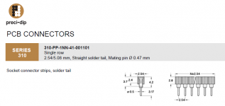
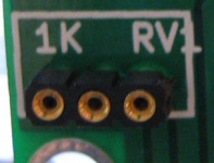
You can buy those pins separately, DigiKey calls them "Solder Tail Female Sockets" and offers them as part number 1212-1114-ND (a strip of 64 socketed pins). Lots of hobbyists call them "Breakaway SIP sockets @ 0.1 inch pitch". A drawing from Preci-Dip's catalog is below. I sometimes use these in my own PCBoards, here's a photo of a "socket" for a trimmer potentiometer that I made by breaking off 3 pins' worth. Naturally you can break off as many or as few contiguous pins as you like.As I am wanting to use this preamp with both MM and MC cartridges, it makes sense to have the resistors that set the gain changeable somehow. Instead of wiring up a switch, which would look kludgey no matter how it's done, I opted to use these pins. Stolen from a really nice DIP socket, they are soldered in, and now the leads from the resistors can be inserted and removed from those pins. A simple solution, and quite handy when I feel like using a low-output moving coil.
Attachments
I recently modified a fully made-up Bugle2 for a friend, so some of you might be interested in my observations:
1. The 60dB Bugle2 came with a 100ohm res soldered into the first resistor position (C23?), as per the Hagtech User Manual. My friend wanted to use it with a LOMC which requires a much higher load - so I removed the resistor ... which left the 47.5K res in position 3 as what the cartridge sees.
2. Then I removed the PCB-mount input & output RCAs (a PITA), so I could mount the PCB in a metal case which had enough back-panel real estate to take:
* the output RCAs
* the input RCAs plus a parallel pair of input RCAs for loading plugs
* the ground terminal, and
* a DC socket to fit the plug on the end of the wall wart.
3. I mounted a LED in the front panel, so the guy could see when the wall-wart PS was plugged in.
4. The box I used was HiFi2000's smallest 'Galaxy Maggiatore' case, with 10mm front plate.
In my system, I did notice much more noise than with my own battery based, JFET phono stage. However, this must be a feature of my system, as we could hear no noise in my mate's system (with ear against the speaker).
However, the wall wart is an SMPS - and I suggest this must be adding sh*t to the signal. (As when I test my phono stage PCBs with a SMPS, I get a too-jagged trace to accurately measure gain - even after regulating it twice with an E-F filter. So I use the SMPS only to set various voltages and then switch to battery power, to adjust gain.)
So I suggest the Bugle 2 will sound better if you build a conventional regulated 24v PS.
Regards,
Andy
Building the Hagerman 'Bugle 2'
The DC starts from a little switch-mode AC-DC adapter outputting 24V DC. It being a SMPS, it has very nice DC coming out from it but it does have some high-frequency hash like they all do.
...
Ok. So what does that mean? It means that at high frequency that PSU rings and makes some 'noise'. (Ultrasonic, BTW, way above the audio band.) This is very common in modern wall-warts.
So how the heck is it fixed? Simple - inductors! (Also known as chokes) Because the current draw of this preamp is fairly low, some high-value chokes can be placed on the PSU input and all the junk and grime hits a brick wall.
Hi 6L6,
What value of inductor did you use, and was it installed at the PSU input to the board?
Thanks
Stuey
i agree.
mlloyd1
mlloyd1
... I just thought the PSU filtering in this kit was really quite clever.
It is a low, but not ultra low noise op-amp. LME 49990is much better at the same price.Opamp in the kit is LM4562 - the OPA2134 is just the label on the schematic.
I used the TO-99 package LM4562 only because I had them and wanted to use them in this project.
- Home
- Source & Line
- Analogue Source
- Hagerman Bugle 2