gotcha!Let me try to see how it simulates and I will get back to you.
Hey... do you doubt my simulator?


Hey... do you doubt my simulator?
One smiles, he saw the light. Then there is one trying to smash the light, but he will be punished.
One smiles, he saw the light. Then there is one trying to smash the light, but he will be punished.
ahahahah!!!! NOOOOOO!!!
I didn't think you had tried that!
I also wondered why you didn't remove one of the RIAA networks. I would convert R17 into 2 resistors i series and ground the middle connection of these 2 resistors to gnd.
I just did.
do you want to ground the series of resistor at the center?
What advantage would you think you would get by doing that?
To me leaving it floating is more immune to noise just an idea.
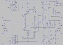
I am attaching the model. It looks like I can't get a solid result.
Could anybody here look at it and make sure I am not making any gross mistake?
Remove the faulty servo
I am attaching the model. It looks like I can't get a solid result.
Could anybody here look at it and make sure I am not making any gross mistake?
Done
Attachments
Done
great! Do you guys feel confident and you want me to sztart prototyping this?
just a question:
on the servo that feeds the input, isn't this going to affect loading on the cartridge?
Let's say, ideal loading on the cartridge is 100ohm, then each side should have 200ohm.
Now with the resistor in series aren't we creating asymmetric condition for the cartridge to work off from?
on the servo that feeds the input, isn't this going to affect loading on the cartridge?
Let's say, ideal loading on the cartridge is 100ohm, then each side should have 200ohm.
Now with the resistor in series aren't we creating asymmetric condition for the cartridge to work off from?
Stefanoo do you feel confident..??
I actually do really like this I am just wondering if we would like to work on the current mirrors and output buffer eventually.
I feel like ouput stage could be selected better.
I will do some listening tests with the Kelvin's buffer and see if it sounds any better than the simple one and eventually include it on the common schematic.
just a question:
on the servo that feeds the input, isn't this going to affect loading on the cartridge?
Let's say, ideal loading on the cartridge is 100ohm, then each side should have 200ohm.
Now with the resistor in series aren't we creating asymmetric condition for the cartridge to work off from?
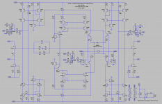
There is 100 Ohm both sides, as that was in your original drawing, there is no problem if you halve the resistor values (3 x 50 and 2 x 100 Ohm) the servo will still work, and the servo output filter will go from 1.5 to 3 Hz (and that is fine too).
But why not leave the 200 Ohm 'standard' loading, and add a resistor of 200 Ohm in parallel to the cartridge to get 100 Ohm loading, by providing a place to add this loading resistor it is easy to change to loading by changing just one resistor, and you can go from 200 Ohm to (almost) zero (we must allow for trace and wiring resistance).
Think I need pants with flared legs for that one, polyester and in ugly brown with thin white stripes.
Ooh, and lacquered ankle boots with a zipper.
http://www.youtube.com/watch?v=kzw1_2b-I7A
Last edited:
- Status
- This old topic is closed. If you want to reopen this topic, contact a moderator using the "Report Post" button.
- Home
- Source & Line
- Analogue Source
- Masterpiece