Done
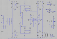
Output Offset 1.3uV
Input Differential 118pV
Servo 1 Output 311uV
Servo 2 Output 550uV
These guys know how to do there stuff, there at the ATL!
Super...
Super...
Is this all you can do, do decent bribe, then I just have to reveal all
") So here it is, the answer was in the fact that a cartridge does not have a center-tab So no real ground needed Now we still need to see that it actually works, have fun testing.
So here it is, the answer was in the fact that a cartridge does not have a center-tab So no real ground needed Now we still need to see that it actually works, have fun testing.Attachments
Is this all you can do, do decent bribe, then I just have to reveal all
What you said is correct.
Cartridge has no center ap which means that input gnd is floating.
Proven fact is that I run it balance with single end cable i.e. no gnd.
The only thing is that the scheme servo corrects directly the input signal which seems to be invasive IMHO.
Any tought on this?
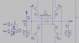
There's is a way that may work with your interfets, sometime ago I (in this thread) showed an N channel fet RIAA. The top and bottom was mirrored over to a current output node. two such circuits can feed the OPA1632, and you can make 2 servos one from each current output node.
Would you like to repost it?
We may take it from there! I would still be interested to try that version to see how it compares to the discrete's.
Btw I just tried the SE version of the circuit here and sound is very, very good.
Fast, detailed, deep base very refined.
The only thing is that the scheme servo corrects directly the input signal which seems to be invasive IMHO.
Any tought on this?
No (and yes), IMO it makes no difference where you connect the servo, as long as it influences the output it is in the signal, as long as it influences the output with surten degree then that 'degree' is the measure, no mather where it is connected.
Is this all you can do, do decent bribe, then I just have to reveal all
Sorry, but I see I made a mistake
I did only servo the 'right' output, and not the left. This can be easily corrected I think, but a third servo is needed. Both 75 Ohm resistors should be driven by separate servo's. For this the center point should be connected to ground, and the other side of those resistors should be servo managed.Btw I just tried the SE version of the circuit here and sound is very, very good.
Fast, detailed, deep base very refined.
Would you post the circuit you built ?
Sorry, mistake
Made me wonder if the L-side could do without, if it was 100% identical to the R-side. (+ same conditions)
Sorta mirror Slave.
Made me wonder if the L-side could do without, if it was 100% identical to the R-side. (+ same conditions)
Sorta mirror Slave.
Would depend on the matching of the transistors. The mismatch on the input BJT's is multiplied by 40dB (that's a lot). Problem is, this does not always show in simulations, as all devices of one type match 100% (in LTspice, in other simulators you can do some Monte Carlo analysis).
(that's a lot)
Hand matching, not talking about simulators.
The 100 percent identical 'conditions' would be the real problem, no idea how to achieve that.
Just a (pre-lunch) mental exercise.
Other mind jump was to take the differential of both outputs and servo it down to zero, plus individual side servo's for the common DC level, but where to inject those ?
Maybe not 100% but on 99% I am working on and is been pre lunch and pre dinner for weeks
Yes Stefanoo, i would also like to see the circuit that sounds so good.
ok I will post it a little later.
It is the SE of the circuit I have already posted here.
After giving this a bit more thought, I come with this for input differential nulling. The previous scheme will not work, the input differential was null due to the fact that the cartridge-model had a series resistance of 0 Ohm (a bikini model would have been just as effective). I upped the series resistance of the cartridge to 50 Ohm and added some offset injection (R58) for testing. This version will work.
For output offset nulling I still have no final scheme, those guys from ATL where not as smart as it seems I do have some alternative ideas to try, but I also need more time, that I sparsely have.
For output offset nulling I still have no final scheme, those guys from ATL where not as smart as it seems
I do have some alternative ideas to try, but I also need more time, that I sparsely have.Attachments
After giving this a bit more thought, I come with this for input differential nulling. The previous scheme will not work, the input differential was null due to the fact that the cartridge-model had a series resistance of 0 Ohm (a bikini model would have been just as effective). I upped the series resistance of the cartridge to 50 Ohm and added some offset injection (R58) for testing. This version will work.
For output offset nulling I still have no final scheme, those guys from ATL where not as smart as it seems
Looking at it, I really think this servo is intrusive.
Basically it corrects right at the input of a 60-65dB normalized gainstage.
Plus the use of the 1m right at the input seems excessive.
Isn't there any different way to correct it?
I am also thinking how much the differential offset will wonder if the stage is built with monolithic BJTs.
Also like I said the differential offset can be corrected between the two legs of the differential input but I was unable to find a suitable circuitry for that.
I am really curious to see what the other alternatives you have in mind are
(a bikini model would have been just as effective)
True, resistance is futile, as you say.
(I'm following this, and at the same time ignoring all ATL suits)
- Status
- This old topic is closed. If you want to reopen this topic, contact a moderator using the "Report Post" button.
- Home
- Source & Line
- Analogue Source
- Masterpiece