Fuse rating depends mostly on the transformer rather than the low power circuitry it powers when considering toroids and small signal stuff like this.
315ma AT sounds a bit small tbh looking at your picture of the transformer. My advice would be that if you get nuisance blowing then move up to a 600ma AT.
Those values assume you are on 230/240 mains.
315ma AT sounds a bit small tbh looking at your picture of the transformer. My advice would be that if you get nuisance blowing then move up to a 600ma AT.
Those values assume you are on 230/240 mains.
Mooly, it's just weird the way Elektor have it written in the project, very unclear.
Obviously, as a mains input fuse, a 0.315A Antisurge is far too low.
Ive actually used a 100VA of the http://uk.farnell.com/multicomp/mcta050-18/transformer-toroidal-2-x-18v-50va/dp/9530380?st=50 va mains transformer
Obviously, as a mains input fuse, a 0.315A Antisurge is far too low.
Ive actually used a 100VA of the http://uk.farnell.com/multicomp/mcta050-18/transformer-toroidal-2-x-18v-50va/dp/9530380?st=50 va mains transformer
It is the switch on surge you have to consider for this design, not the maximum load current the transformer could support, and the surge is something that will differ each time you power it on as it is dependent both on any magnetic residue in the core and also the point in the cycle you apply power.
Its not worth worrying over excessively.
If you want to try the 0.315A then its fine to do so, but if it blows regularly on switch on then you need to work up in value.
My Marantz CD player uses a small toroid and that is protected with a 1.25AT fuse.
Its not worth worrying over excessively.
If you want to try the 0.315A then its fine to do so, but if it blows regularly on switch on then you need to work up in value.
My Marantz CD player uses a small toroid and that is protected with a 1.25AT fuse.
")
Having powered up, i get no sound output.
The supply voltages are all ok, +17, 0 and -17v.
D1 led also lights when powered on.
D2 led i have not seen lit, despite numerous combinations of S4/S5 etc.
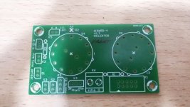
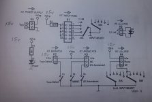
My question is to try and clear up the position and mounting of S4 and S5.
Both these rotary switches can be mounted any way on the Front panel pcb.
Can someone please advise?
The supply voltages are all ok, +17, 0 and -17v.
D1 led also lights when powered on.
D2 led i have not seen lit, despite numerous combinations of S4/S5 etc.
My question is to try and clear up the position and mounting of S4 and S5.
Both these rotary switches can be mounted any way on the Front panel pcb.
Can someone please advise?
I see no one has replied.
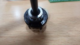
I've not studied the switching arrangements but those Lorlin switches would be symmetrical electrically as regards the contacts. I am assuming they are a two pole six way switch and not a one pole twelve way.
You can prove that yourself by simply measuring which pins connect to the centre terminals on the switch for any given position.
Rotate the switch 180 degrees and confirm nothing has changed with regard to the way the switch will operate. i.e. the same pads on the board will be linked by the switch irrespective of position.
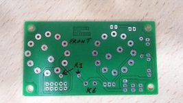
+Vre / K6 socket
Thanks Mooly for that.
I switched on my Preamp 2012, but i get no sound output.
The supply voltages are all ok, +17, 0 and -17v.
D1 led also lights when powered on.
D2 led i have not seen lit, despite numerous combinations of S4/S5 etc.
My question is to try and clear up the position and mounting of S4 and S5.
Both these rotary switches can be mounted any way on the Front panel pcb.
Can someone please advise how exactly they should be mounted?
Lastly, to enquire about K6 socket and the +Vre/0 connections.
Following +Vre from the PSU to K6, you'll see that the +Vre on K6 does not go to R1 !
Attachments
Last edited:
Front Panel pcb
Cct attached.
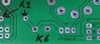
K6 has to be wrongly marked!
The +Vre/0 supply (from PSU K4 ) is connected to the Front Panel pcb K6.
You'll see K6 is incorrectly marked on the pcb!
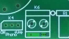
K6 on the pcb marking +Vre should be 0 and 0 should be +Vre
Cct attached.
K6 has to be wrongly marked!
The +Vre/0 supply (from PSU K4 ) is connected to the Front Panel pcb K6.
You'll see K6 is incorrectly marked on the pcb!
K6 on the pcb marking +Vre should be 0 and 0 should be +Vre
Attachments
Last edited:
Cct attached.
K6 has to be wrongly marked!
The +Vre/0 supply (from PSU K4 ) is connected to the Front Panel pcb K6.
You'll see K6 is incorrectly marked on the pcb!
K6 on the pcb marking +Vre should be 0 and 0 should be +Vre
Not so! Take a look at the photo in the published article ( Elektor June 2012 P24). As viewed from the topside of the PCB, +Vre is marked as the leftmost of the two connections of K6 and 0V is marked as the rightmost connection. This is correctly shown.
Geoff
That's true about the images on page 24.
But.....
Follow the +Vre on K6 and it's supposed to go to R1......
I've had a closer look at the photos in Elektor June 2012 article and you are probably right. To confirm this, +Vre on K6 should also go to +Vre on K2, K3 and K4 - verify which location of K6 corresponds to this.
Geoff
Yep,
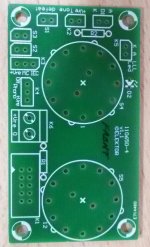
on my Front Panel pcb, K6 is labelled wrong!
It's 0 that connects via the print to +Vre on K2, K3 and K4.
K6 should have been labelled looking at the top side (not print side) with 0 on the left and +Vre on the right.
K6 now labelled correctly!
Ive brought the matter to Elektor's attention seeing that the kit of pcb's were purchased from them.
Attachments
Last edited:
Apparently these boards are still available direct from Elektor.
SET OF THE 6 PCB'S PREAMPLIFIER 2012 (110650)
SET OF THE 6 PCB'S PREAMPLIFIER 2012 (110650)
- Status
- This old topic is closed. If you want to reopen this topic, contact a moderator using the "Report Post" button.
- Home
- Source & Line
- Analogue Source
- Doug Self's New Preamp Construction and Pictures