Bonsai - That's a switch assembly that comes standard on many kits I've bought from my ebay supplier(along) in China. He normally doesn't sell them separately, but he will if you want one. You can't see it in that picture, but there's a LED in front of the assembly that makes the switch glow when powered on. You do have to run 5VDC to the switch to power the LED. But, it can be easily modified by simply using a cable from a PCB where the LED would normally go.redjr, thats a very nice mains switch assembly (switch + screw terminals and mounting bracket) you have on your front panel. Is that a bought in assembly, or did you build it up yourself.
Awesome job BTW - I am looking forward to your assessement of the sound once completed.
That switch is almost identical to mine. It too came from China in a chassis kit. One gave a nice blue glow the other gave a yellow glow.
So much for Chinese quality control or complete lack of it.
The tapped slots to hold on the front and back were/are attrocious. I have not found a solution yet.
So much for Chinese quality control or complete lack of it.
The tapped slots to hold on the front and back were/are attrocious. I have not found a solution yet.
I prefer the blue glow, but at least you can put whatever color LED you like in. I've never had any problems with the mounting holes - either on the switch assembly itself, front panel.That switch is almost identical to mine. It too came from China in a chassis kit. One gave a nice blue glow the other gave a yellow glow.
So much for Chinese quality control or complete lack of it.
The tapped slots to hold on the front and back were/are attrocious. I have not found a solution yet.
It really is a nice little assembly and convenient if you want a lighted, pushbutton switch. You can email along here.Thanks.
Looks like the best way forward is to roll my own.

different chassis........... I've never had any problems with the mounting holes - either on the switch assembly itself, front panel.
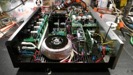
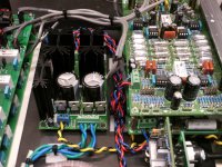
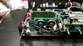
Here are a few more pics of my progress. If these are boring everyone, let me know and I'll quit posting them. I'm waiting on some new knobs before I can lock down the exact location for the front panel switch/control board. I now have only the control cables to attach and install the 3 micro toggle switches on the front panel.
Attachments
I did a couple momentary power ups tonight after all final wiring was done and heard a click (what sounded like one of the relays). Keep in mind there was no input signal, so I'm not sure if this 'click' is normal for the preamp or not? I didn't leave it on for any length time, but did not notice in magic smoke either. Thoughts?
There are two relays used in the tone defeat circuit, but I would expect they would only be energized with the defeat switch on. In the default mode, the relay is not energized. There is no mute function available on this preamp, and there are no other relays shown in the schematic, or on the block diagram as published for the main preamp board.Isn't there a mute relay in the preamp?
It's late tonight so I'll do some trouble-shooting tomorrow when my mind is fresh.
It's quite possible I have some mis-wiring somewhere causing the click. I've been pretty meticulous and very methodical with my wiring, but mistakes can still be made. I suspect it is a relay. Now that I think about it, since relays are also used on the inputs boards, the click may be the relay for the of whatever input is selected by the selector switch when it is powered on. That makes a lot of sense now.
Last edited:
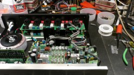
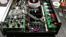
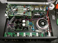
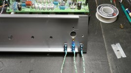
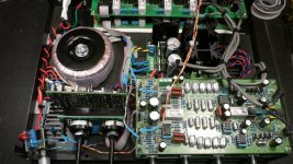
Here are a few more pics of my preamp sans the front panel. I took an unusual approach in fastening my micro-toggle switches to the FP. Since the FP is 8mm thick, I used J-P Weld metal glue. Hopefully, it will stand the test of time with these switches that will probably see little usage.
Attachments
That initial low click that I hear on power up does not seem to be the same click that you hear when the input is changed. Those are louder because you're hearing two relays click in tandem. The first click is very low sounding. But I have other troubles...
I tested this morning with an input signal and power amp attached. I can hear the source relays click, but I'm not getting any audio at all, and what sounds like a high frequency oscillation for about a 5 sec and then a louder cracking sound.
My question is... from a process of elimination trouble-shooting standpoint, I should be able to remove all the LLLL and Input related PCB intra-connects - right? Next I should be able to power up the main board separately from the input board and attached RCA jacks in/out to test just that board. Any problems with doing that? I also have a hum issue.
Doug states in the article that the "audio ground and the relay ground must be connected together at one point only, right back at the power supply". Is this implied in the intrinsic design using the intra-connects, or is it a separate wire hookup. If so, exactly what relays is he referring to?
By process of elimination hopefully I'll find the problem, and just hope it is not a device issue on one of the PCBs. I don't have any test gear other than a DVM, so I'm limited on what and where to look.
Rick
Last edited:
Ok, I feel like a dummy asking this question but here goes... throughout this design there are numerous 4-pin connectors used for the signal. The outside pins are labeled R+ and R-, and the 2 center pins for ground. RCA jacks only have 1 signal pin (center) and ground(shield) or casing. Are the R+ and R- required when using XLR jacks? Don't get me wrong, I have used 4-pin intra-connects for all 4-pin headers on the PCBs.
If I want to test my preamp board only using these 4-pin input/output headers, what 2 pins do I use? R+ and ground, or R- and ground? I have never used XLR jacks before, so I'm not familiar with there pin designation - although I do know they are used for balanced input. I did however include them for project completeness - having them available for future use should I decide to use them.
Even with just using the main board (I/O), I'm still getting the same symptoms, but I may have used the wrong pins for my test.
Thx,
Rick
Edit: After reviewing the schematics I can see that the RCA connectors are tied to R+ and ground (as I suspected).
Last edited:
Update.... I now have sound. Since I was having the same symptoms with the main PCB disconnected from the other circuitry, I knew it must be an issue there. After a close examination I noticed 1 IC that was installed backwards. You know, those pesky little ICs must be installed correctly to work right! That's the kind of problem I can deal with.
I haven't done any serious listening with it yet, and while I don't even own a preamp of this caliber, what I'm hearing I like. I'm sure it won't disappoint. BTW, I put a test speaker up to ear and it is dead silent - at least audibly. Perhaps the right test equipment could find some.
I'm still having a little trouble with the LLLL LED working, so I have to check that out still.
You know, those pesky little ICs must be installed correctly to work right! That's the kind of problem I can deal with. I haven't done any serious listening with it yet, and while I don't even own a preamp of this caliber, what I'm hearing I like. I'm sure it won't disappoint. BTW, I put a test speaker up to ear and it is dead silent - at least audibly. Perhaps the right test equipment could find some.
I'm still having a little trouble with the LLLL LED working, so I have to check that out still.
Can someone explain to me just how the Log-Law Level LED indicator works and the real value it adds to adjusting, or using the 2012 preamp? The reason I ask is, I've just about finished up construction on this project and I'm getting no response from the LLL LED. I'm assuming it should be displaying something, but despite Doug's description in the Elektor article, I'm still a little fuzzy on its purpose and implementation and what to expect. At this point I believe my board is faulty, since I've double checked everything else and it seems correct.
log law is roughly equivalent to dB scaling.
If you have steps of 3dB from +6dBfs all the way down to -30dB then that is true log law.
A log law taper on a volume control pot tries to achieve something close to this, but never is anywhere close. A switched attenuator could get accurate log law to exactly mimic the dB steps you design for.
If you have steps of 3dB from +6dBfs all the way down to -30dB then that is true log law.
A log law taper on a volume control pot tries to achieve something close to this, but never is anywhere close. A switched attenuator could get accurate log law to exactly mimic the dB steps you design for.
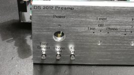
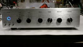
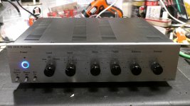
Update... The DS 2012 preamp is finished! It's been a long haul, but I'm very happy with the end result. I went with a little different look with the black knobs on a silver FP. I think it looks kind of 'smart' personally. I wasn't quite sure which would look the best, silver, or black. I do have a set of silver knobs should I want a more conventional look down the road. Finding just the right, proportioned sized knobs proved very interesting to say the least. You just can't tell what they will look like unless you try some physically. So now I have bin full of different size sets of knobs - some larger, some smaller. These are the best looking ones in my opinion.
If I can give a shameless plug for Front Panel Express. As I mentioned in an earlier post, this was my first time trying them and I can say I was pleasantly surprised by the high quality of their service. Their software is fairly easy to use and for one-off panels their price is fair. I couldn't have even come close with a drill press and press-on lettering! I highly recommend their services.
Thanks again to Doug Self for designing and publishing this fine preamp project and Elektor for making available the PCBs. This pre is obviously a real contender, and certainly eclipses, in audio performance, the rest of my non-esoteric gear. But, I wanted this DIY project as a challenge and I'm glad I took the many months to see it through to completion. I'm very satisfied with the result.
Rick
If I can give a shameless plug for Front Panel Express. As I mentioned in an earlier post, this was my first time trying them and I can say I was pleasantly surprised by the high quality of their service. Their software is fairly easy to use and for one-off panels their price is fair. I couldn't have even come close with a drill press and press-on lettering!
I highly recommend their services.Thanks again to Doug Self for designing and publishing this fine preamp project and Elektor for making available the PCBs. This pre is obviously a real contender, and certainly eclipses, in audio performance, the rest of my non-esoteric gear. But, I wanted this DIY project as a challenge and I'm glad I took the many months to see it through to completion. I'm very satisfied with the result.
Rick
Attachments
Thanks Bonsai. It's a big project, but if planned right and executed well it will be worth it. Lots of details and a myriad of internal wiring. One piece of advice... use a big chassis. That's the one thing I'd do differently. Mine was just a bit to small and it became difficult to work inside once things started to get put in place. Luckily, I have narrow fingers so that helped.
Hope to do more serious listening this weekend, so will report back on how it sounds. Initial, quick tests on my bench sounded very good indeed.
Rick
Hope to do more serious listening this weekend, so will report back on how it sounds. Initial, quick tests on my bench sounded very good indeed.
Rick
- Status
- This old topic is closed. If you want to reopen this topic, contact a moderator using the "Report Post" button.
- Home
- Source & Line
- Analogue Source
- Doug Self's New Preamp Construction and Pictures