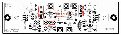
To get back to the Paradise build, just finished unsoldering and resoldering the capacitors on the Calvin boards, because the silkscreen and the markings on the PCB seem to be in conflict with the traces on the PCB.
The image shows the actual connections on the PCB.
The image shows the actual connections on the PCB.
Attachments
Gentlemen, i have a lot of respect for the people who designed and developed this unit, and spent a lot of time and trouble to make it work. I can understand that after a few years and more than 400 pages you get somewhat fed up with the project and ignore the troubles and problems of those who decided at a late hour to attempt this difficult task.
Yet i hoped there would be a trace of compassion left to give a brief answer to what must be very simple problems for those in esoteric strata.
In post #4297 i asked about capacitors C901, 901-1, 901_2, ... and was told (thank you very much Si)
"Sebs boards don't have the 9x 1uf smt caps. They were on the underside of the original boards."
So next i asked
"How important are these 1uF caps, i wonder? Could get MCC's and solder them on the bottom if needed."
I had to ask because my knowledge of electronic circuits is far from being able to find an answer, and still do not know what to do.
I can understand that after a few years and more than 400 pages you get somewhat fed up with the project and ignore the troubles and problems of those who decided at a late hour to attempt this difficult task.
Suggest that you contact diyAudio member Joachim Gerhard.
Sebs boards doen't have them, you'd need to scrape the gnd plane off in many places to fit them, its not in any way practical to implement them. Ive built three on sebs boards, never had issues without them. Ime stick to below 450hfe and match super carefully and its not an issue.
Thank you all.
Have already ordered caps, but if careful matching will do the job, i'd rather do that.
@hesener Yes, i am trying my best to follow it. Even found the Assembly Guide in German in your Link List - downloaded and printed. Very useful because now i don't have to use my poor English.
Have already ordered caps, but if careful matching will do the job, i'd rather do that.
@hesener Yes, i am trying my best to follow it. Even found the Assembly Guide in German in your Link List - downloaded and printed. Very useful because now i don't have to use my poor English.
Not to worry, mine is non-existent 
I could use some help, however:
The two 10 turn trimmers R106 and R206 are marked 100k both on the silkscreen and on the PCB, yet the Parts List asks for 2k.
That seems a rather large change to me, considering that nothing else around it has changed
Where could i find out which value is correct?
Thank you.
I bought some Paradise boards made by one of the guys from here but they don’t seem to have any of the compensation caps fitted .While regulator caps is not a problem as I can solder them underside I’m not certain about SMD in the amplifier stage , anyone built these new boards without SMD caps with no problem with oscillations?
One more question about transistors matching , input stage works at around 14V and low current , looks like 3-3.5mA and mirrors low voltage , around 3V without looking at the circuit and 14mA , is this correct ? I was thinking about marching them on DCA 75 but 14V is above its range ,
One more question about transistors matching , input stage works at around 14V and low current , looks like 3-3.5mA and mirrors low voltage , around 3V without looking at the circuit and 14mA , is this correct ? I was thinking about marching them on DCA 75 but 14V is above its range ,
It seems I am blind and have missed your post regarding SMD caps , I take you have tested boards with a 70MHz or higher scope ?Sebs boards doen't have them, you'd need to scrape the gnd plane off in many places to fit them, its not in any way practical to implement them. Ive built three on sebs boards, never had issues without them. Ime stick to below 450hfe and match super carefully and its not an issue.
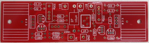
Just in case , could someone remind me position of this capacitors , these don't seem to be included on the schematic and my old boards stayed in UAE but I'm stuck in Europe for God knows how long , good time to build Paradise from scratch

Could someone confirm working conditions of input and mirrors transistors , I'm thinking about little matching jig after preliminary DCA 75 testing , thank you

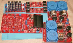
Defluxed, rinsed, reflowed, inspected and deoxit'''d | Flickr
Caps shown on underside of original boards. They can all be fitted by removing some solder mask.
Yes, I measured with a 100mhz scope.
Caps shown on underside of original boards. They can all be fitted by removing some solder mask.
Yes, I measured with a 100mhz scope.
- Home
- Source & Line
- Analogue Source
- Paradise Builders