Well, have just put an ad in the Wanted section, maybe somebody has a used one they no longer need 
Is that of any importance? Excerpt from Store:
Note: The DCA Peak Atlas Pro semiconductor tester will give inaccurate results for testing these JFETs as it cannot provide adequate current during the test. Please refer to the user manual for more information on its specifications. This is a great tool but should not be used for testing high current / high voltage devices.
If Idss is high it only reports "Idss > 12 mA". I can confirm that. Tried to test J310. Not enough current do that. Other parameters are displayed.
It is also a "small signal" curve tracer when connected via USB. PC is then the display. Joachim showed some of those screenshots smoewhere in this (or MPP) thread.
It is also a "small signal" curve tracer when connected via USB. PC is then the display. Joachim showed some of those screenshots smoewhere in this (or MPP) thread.
")
Just a small thing, but i need help with the fuse holder for the pre-reg: the pitch on the PCB is a bit more than 24mm, but fuse holders i found have pitch of 22.5mm. I suppose it is possible to bend the pins a bit, but i would prefer to use the correct size.
Would somebody be kind enough to help me out with a link?
Would somebody be kind enough to help me out with a link?
Si beat me to the response. Thank you to both of you.
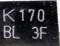
Interestingly the 170's i bought earlier with a marking quite different from the Tosh one are shown to be N-Channel JFET's by the DCA75, but the Idss range was between 5 and 5.8mA. In order words - no fakes, but a bit out of spec.
Interestingly the 170's i bought earlier with a marking quite different from the Tosh one are shown to be N-Channel JFET's by the DCA75, but the Idss range was between 5 and 5.8mA. In order words - no fakes, but a bit out of spec.
Attachments
Not really a problem, so possibly it was rightly ignored.
I'll try a couple of questions this turn, maybe there is still somebody not only reading this thread, but also willing to help somebody learning?
The Feb 2020 update of the Parts List shows SMD
Caps C901, 901_1, 901_2, ....
I can not find any place on the PCB (top or bottom) where they might fit.
Search came up with a post of Karel's from 2013, but nothing after that. These caps are also shown in the Assembly Guide.
Just a small thing - are there special screws to fasten the Preamp heat sink to the PCB? The channel where the three screws should go is riffled, but of course a standard M3 screw will not fit. No big deal to tap M3, but it looks as if there should be an easier way?
Thank you.
The sk75 heatsink takes standard m3 8mm screws, its tricky though.
Fit the thermal pad to the heatsink, fit one central screw, you'll need to wiggle the heatsink as it creeps sideways as you screw it in and alignment has to be perfect. Then fit and clamp each t220 part in turn, I use a small trigger G clamp to fit the spring clips. Then check they don't overlap the edge of the heatsink, then solder in place and fit the last two screws. Sebs boards use a slightly wider spacing than the original board, so you might need to tilt the t220 parts on each end inwards slightly.
Sebs boards don't have the 9x 1uf smt caps. They were on the underside of the original boards.
Thank you, that helps.
Since i do not have any clamps (did not know that i should have ordered them) i will have to drill and tap M3 for each transistor. I did know enough to get insulating kits, so that should work ok. Will also tap a couple of threads in the bottom of the heat sink to make starting the screws easier and prevent them from wandering.
How important are these 1uF caps, i wonder? Could get MCC's and solder them on the bottom if needed.
Si beat me to the response. Thank you to both of you.
Interestingly the 170's i bought earlier with a marking quite different from the Tosh one are shown to be N-Channel JFET's by the DCA75, but the Idss range was between 5 and 5.8mA. In order words - no fakes, but a bit out of spec.
That mark looks fake, especially "K".
- Home
- Source & Line
- Analogue Source
- Paradise Builders