Finally getting back to my Paradise build after, oh, what, five or six years? LOL
The poor boards have been starting at me in my storage room, all resistors nicely installed but nothing else. So I am back to matching transistors. I'm using the little circuit posted by hesener and would like to know if it's ok to plug in transistors one by one while the circuit is energized, or if it's better to remove the power before testing each part? Thanks!
The poor boards have been starting at me in my storage room, all resistors nicely installed but nothing else. So I am back to matching transistors. I'm using the little circuit posted by hesener and would like to know if it's ok to plug in transistors one by one while the circuit is energized, or if it's better to remove the power before testing each part? Thanks!
If there is any stored charge the transistors can go into avalange and get noise.
This is particular true if they are revers biased. i do not know if Herseners circuit does that or not. i hope he replies.
Sofar i have not heard of any problem though.
Thank you Joachim, I will add a push button to apply the power so that there's no risk to the parts. Better safe than sorry!
I now have all my transistors tested and grouped. It looks like I will have enough for the input sections all around 420-460.
So, for the current mirrors and power supply, can there be a large mismatch between NPN and PNP groups as long as the part within each group are matched? Do we prefer low or high current gain values here? What about the BC parts in the regulator...I assume lower current gain here is better?
And, as I am reading through this massive thread but itching to get going, there are some discrepancies and missing items between Alfred's BOM and schematics and I am hoping for clarification:
There are spaces for nine SMT caps, some across the mirror resistors and three under the links connecting the regulator to the RIAA. Do we populate all these? What is the correct type/value/voltage?
R100, 103, 200, 203 are 330R on the schematic and 120R on the BOM. Which is correct?
Should the 1uF bypass caps across the input electrolytics be installed or not?
Thank you!
As I am now going for a Calvin Buffer preamp with prereg, it will bring up some questions.
Shall I post and ask here, or is there another/better thread somewhere?
I used the Calvin Buffer with just some 78xx and 79xx powersupply. It sounded ok.
Now I tested it with the prereg and this is in a complete other league.
Still it does't have the "glow and organic sound" of my mcintosh C39 preamp. Although the Calvin has much better resolution.
Is it necessary to match the fets and bipolars?
Also, I use a Blue Alps volume pot. There are better ones. Maybe something with remote would be cool... Someone have an idea?
Should I build a new pcb with a opamp to regulate the dc offset? Will the opamp regulate in case of a problem, like loss of one psu rail?
Regards, Remco
Hi,
while matching typically improves figures it might not be needed here because of the offset trimpot in the negative part of the buffer.
Still though I´d recommend to match the input (master) JFETs and to also couple them thermally ... or use dual matched types in first place.
As alternative for the Alps You may look for the -quite alot costier- TKD CP2500 which is also available with motor.
Be careful though as the TKDs casing and pins are very sensitive thermally and mechanically.
Other options include solidstate potis like the CS3301 or its TI´s equivalent.
I´m not sure where You want to put a dc-servo.
I showed a servo for the buffer in the associated thread.
It seems though that the users who implemented the buffer with the paradise phono never had a problem regarding offset or offset drift.
In any case when a supply line is lost no servo can cope with that.
Even a dc-blocking cap would put out a temporary spike voltage.
jauu
Calvin
Replying to my own post to help any others who might stumble on the same inconsistencies. It also is unfortunate that this thread evolved into a Paradise+Calvin thread about 75% the way through which makes it VERY difficult to follow if the discussion is related to the Paradise or Paradise+Calvin. Splitting off as a separate thread would have made things much easier, but it's my own fault for sitting on this project for so long. Anyway...
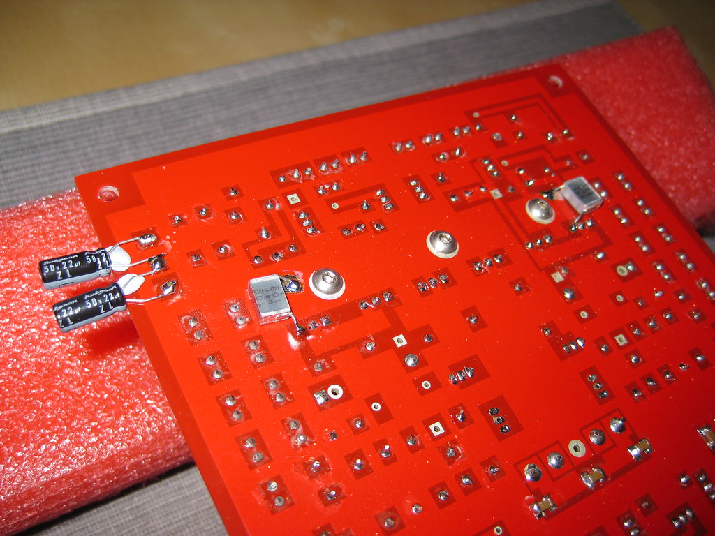
The SMD caps are all 1uF 1206 ceramics. This IS on the BOM, I missed it.
R100, 103, 200, 203 WERE changed to 120R from 330R to reduce the chance of CCS oscillation. This, along with a change of the J310 parts in the CCS to J113 with Rg changed to 1k seem to be important.
From what I can see some have installed the 1uF bypass caps, others have not. I'll leave them out for now and see what happens.
I now have all my transistors tested and grouped. It looks like I will have enough for the input sections all around 420-460.
So, for the current mirrors and power supply, can there be a large mismatch between NPN and PNP groups as long as the part within each group are matched? Do we prefer low or high current gain values here? What about the BC parts in the regulator...I assume lower current gain here is better?
And, as I am reading through this massive thread but itching to get going, there are some discrepancies and missing items between Alfred's BOM and schematics and I am hoping for clarification:
There are spaces for nine SMT caps, some across the mirror resistors and three under the links connecting the regulator to the RIAA. Do we populate all these? What is the correct type/value/voltage?
R100, 103, 200, 203 are 330R on the schematic and 120R on the BOM. Which is correct?
Should the 1uF bypass caps across the input electrolytics be installed or not?
Thank you!
Ungie,
I match everything to 1% including the mirrors ( I actually curve trace the input stage to get a better match at operating temperature).
RIAA to a couple of PF and use 0.1% resistors.
Use J113 on the back end of the shunt with 1k.
Fit the smt caps underneath, fit the 2.2n and 470pf caps to the shunt, see additional pic below for further shunt stability mode from Werner. (22uf/50v and 68n) Only use it if you need it.
Oh and red LEDs are quieter...
I'm not normally a fan of in depth matching just for the sake of it, many circuits don't need it, the Paradise certainly benefits from it. 5% is ok, but 1% is clearly better to the ears. I would advise that you try to match the input stage to within +/- 5 hfe and at 23-25 degrees.
Herzlichen Dank Calvin für deine ausführliche Antwort! ")
Thanx a lot Calvin for your detailed answer!
I have the Calvin Buffer for around 3 years now, in use on and off. I never corrected the offset as this was not needed. And the Paradise Phono with Calvin Buffer in use 4 years in a row, there everything is stable also.
I was just curious what to do in case of a problem with one of the psu rails. But as the Opamp against offset can not work in case of emergency, than I leave it like it is.
Now I have to pair the InputFETs...however this is done ;-)
As of the Volumepot, thanks for your input. The TKD has a good reputation.
Thinking of a Khozmo, but that is around 400€ with remote.
Now reading into the MUSES72320. Sounds very nice....just where to supply it in Europe...
Maybe I'm going to order one in USA.
This electronic Volume Chip needs a cap on In and Output, so DC won't be a issue than anymore.
Schöne Grüße,
Remco
Thank you for the info sq225917! It seems as though everyone built their Paradise long ago and are now onto other things. One last nagging question regards the JFETs in the amplifier section. The original BOM calls for 2SK170 and J310 and the group buy parts kit came with J107 and J109. It looks like J107 is ok, but what about using J109 for Q90, 91, 92? Would J113 be a better choice here as I have extras after ordering for the shunt?
Thanks!
Thanks!
Takes me to correct #1982
Until Jason will take the forum to a new platform there are various buggy things going on with browsers it seems. I have copied the original post's text four posts above anyway.
That makes for 33n3 12n 9k1 67k8
Does it mean that 34.7 nf Salas RIAA value in Paradise R3 assembly guide is not correct?
I can only find this alternative in the R3 guide:
"The values given above and also in the schematic will give you the groovy Joachim-Gerhard –
Michael-Borresen house curve, and if you want to go a tad more linear, you may want to use the
values that Ricardo Cruz has calculated (11nF, 32,1nF 9.9K and 73.7K)"
No mention to an alternative after my suggestions. Unless there was also a minor guide revision I did not store.
I can only find this alternative in the R3 guide:
"The values given above and also in the schematic will give you the groovy Joachim-Gerhard –
Michael-Borresen house curve, and if you want to go a tad more linear, you may want to use the
values that Ricardo Cruz has calculated (11nF, 32,1nF 9.9K and 73.7K)"
No mention to an alternative after my suggestions. Unless there was also a minor guide revision I did not store.
There are Salas alternatives in Paradise R3 guide version 5 assembly guide. Is 33.3 nf a right value?Paradise R3 assembly guide V5.pdf - Google Drive
There are Salas alternatives in Paradise R3 guide version 5 assembly guide. Is 33.3 nf a right value?Paradise R3 assembly guide V5.pdf - Google Drive
If you want to have a "Loudness effect" RIAA you can use the original paradise RIAA values:
9k1 ohm ; 73k5 ohm; 33.3nF ; 11nF (More bass, more treble, mid freq dip)
For a mathematically calculated value according to S: Lipshitz formulae you can use:
9k9 ohm ; 73k7 ohm ; 32.1nF ; 11nF (Quite linear response)
For acquiring Salas build version you should use:
9k1 ohm ; 67k8 ohm ; 34.7nF ; 12nF (Lean, clean deep fast bass)
All of those work but they are system dependent.
You might want to start with 9k1ohm and 32.1nF providing you 317.79us (almost perfect RIAA 318us) and than tune the trebble cap (11nF).
Lowering this treble cap increases trebble.
The 73k7ohm resistor mostly affects bass but it is heavily related to C6a C6b C7a C7b values and capacitor types.
All curves will work but....
You can also simulate the rig and decide the best curve for your build.
- Home
- Source & Line
- Analogue Source
- Paradise Builders