I've. Built with the bom parts, 2140 and opa627BP. There's no audible difference though I suspect the 627 is more stable over temp range. It doesn't really matter once it's up to temperature.
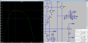
Swapping the 1m resistor for a 5m, slows the servo operation. If your input stage is very well matched this will improve the bass, better tonality, more solidity.
Swapping the 1m resistor for a 5m, slows the servo operation. If your input stage is very well matched this will improve the bass, better tonality, more solidity.
A slightly faster servo may be beneficiary in (more than) two ways.
1: 10...20Hz servo's remove low frequency rumble Rumble (noise) - Wikipedia
2: 10...20Hz servo's lower 1/f (flicker) noise Flicker noise - Wikipedia
3: ...
Actually I should have said 100ms...50ms servo")
1: 10...20Hz servo's remove low frequency rumble Rumble (noise) - Wikipedia
2: 10...20Hz servo's lower 1/f (flicker) noise Flicker noise - Wikipedia
3: ...
Actually I should have said 100ms...50ms servo
Last edited:
Hi ste, the input transistors are running at 3mA each, in the circuit the VCE is around 14V. The DCA75 can be set from 3V...9V, so I would go for 9V. Most important is that all mesure the same, the VCE is not so important.
I compared results with different test voltages. I was surprised by the effect of Vce. If for instance, matching were done with a Peak DCA-55, there would be quite a difference in hFE between PNP and NPN sides at operating voltage. I maintained temp around 24C and repeated with other 337/327
BC327 DCA-75 curves at 9V ,3mA =hFE 483, Test function (DCA-75) = hFE 440, Test function (DCA-55) = hFE421
BC337..................ditto ....................444 ....................ditto ..................434...................... ditto ...............422
I am rather late to the party and I'm sure this must have been discussed previously. I am only on p400 of MPP!
Assuming I am using the DCA-75 curves correctly, many Paradise builders having matched transistors using the DCA-55/75 test function apparently have poor matching between pnp and npn transistors at normal operating voltage.
I set my tester to produce one curve in hFE vs Vce=9V and read value at Ic=3mA.
BC327 hFE increases much more than BC337 hFE with higher Vce
It appears the circuit design effectively compensates for some 10% or greater mismatch between BC327 and BC337 even in the input stage. Being in the process of building this amplifier I would appreciate any clarification that would help me with transistor selection.
At what freq. does your Paradise cut off with these changes?
Did you remove half of capacitance and 1uF bypasses from all emitters - 4700uF &6800uF ?It was measuring 62dB on mine (Rev2 PCB). My RIAA values twist was Paradise Builders - Page 199 - diyAudio
I had also used half the total mF at the emitters and deleted their bypasses. For earlier subsonic roll-off.
Did you remove half of capacitance and 1uF bypasses from all emitters - 4700uF &6800uF ?
The 6800uF doubles are the input stage emitter bypasses, there I deleted one per side. The 4700uF doubles are part of an RC filter with 120Ω resistors for each rail, they won't influence the infrasonic curve. You may keep them all four. And yes, I deleted those 1uF. To avoid possible resonances with the large capacitors supersonic impedance which may lead to some sharpness. Again if you like the result with those 1uF, keep them.
Hey guys.
I've build the Paradise Phono incl. Calvin Buffer in 2014 and its great.
Now I build the Calvin Buffer with the shunt regulator. As I understand, the shunt reg needs a certain amount of current to work like it should.
With the Paradise +Calvin the resistor has to be around 10ohm.
As the Calvin Buffer alone just takes 30mA, what to do?
As I understand, the resistor should be 20ohm. Is that right?
Than I need another prereg... Maybe sq has some left? [emoji12][emoji344]
Regards, Remco
As I have published record-player-cabling-systems before I feel obliged to inform you that I did it again if you are interested have a look at this thread:
https://www.diyaudio.com/forums/analogue-source/328015-grounding-tonearm.html#post5562425
if you are interested have a look at this thread:https://www.diyaudio.com/forums/analogue-source/328015-grounding-tonearm.html#post5562425
Yes lots of people probably have God awful matching and aren't seeing the full performance of the circuit.
Any conclusion on this discussion? I am rebuilding my paradise and this is a good moment for me to do fine tuning, including tranies replacement if this can make this gem sound even better.
Any conclusion on this discussion? I am rebuilding my paradise and this is a good moment for me to do fine tuning, including tranies replacement if this can make this gem sound even better.
Why are you rebuilding it ?
Why are you rebuilding it ?
I guess recurrence of audiophilia strikes again
As usual after some time you realize that you could perhaps do some bits and pieces a bit better. So I am going to optimise enclosure and have another look at trannies etc.
- Home
- Source & Line
- Analogue Source
- Paradise Builders