Well, I avoided the film bypasses on the lytics and it worked...")
Hmmm...
My boards do not have provision for C91 or 92.... no place to put themMaybe this could be tested by not stuffing C91, C92 and C93, then (when tested) add C91 and C91, and then after testing, stuff C93. WOuld you do that?
I used C93 0.1u ok (No C91 or 92)
Just did not bypass C3 C4 C6 C7
I think you should place C3, C4, C6 and C7. They are no issue in the PSU oscillating debate
My boards do not have provision for C91 or 92.... no place to put them
Oeps, I never checked that, in my opinion there is no need for these
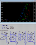
and the circuit will do fine without them. Also, if C91 and C92 not implemented, and no stopper resistors of 10 Ohm in the power line, the C93 may not be needed, and could be a hazard. So then new question to Salas is: Do not stuff C93 (the 100nF on the PSU near the opamp) then test without, and later test with the 100nF stuffed.Now I needed to do the sim's, these are the results, the 2SC/SA's look really good. It looks also the compensated version (tst4) will never be able to oscillate, the phase line is near to straight (o.k. not straight but less then 60deg). Uven the un-compensated 2SA never gets to 90deg.
Attachments
Last edited:
Very nice! Just out of curiosity, what are the blue caps you use in the RIAA section?
EMZ KP72's 1% film/foil, I hope they sound good.
I think you should place C3, C4, C6 and C7. They are no issue in the PSU oscillating debate
I use C3 C4 C6 C7 EL caps off course... just did not bypass them.... Anyway I do not like the effect of bypassing EL caps
I use C3 C4 C6 C7 EL caps off course... just did not bypass them.... Anyway I do not like the effect of bypassing EL caps
But, would you (temporarily) add them, and then listen, you can always remove them. Would be a nice 'experience'-fact. And I am talking about the bypasses
not the EL-caps (I know you knew, but just to be clear on this).
Last edited:
Ok... I will try on C6 C7 first and post my subjective listening impressions
Cool

Now I needed to do the sim's, these are the results, the 2SC/SA's look really good. It looks also the compensated version (tst4) will never be able to oscillate, the phase line is near to straight (o.k. not straight but less then 60deg). Uven the un-compensated 2SA never gets to 90deg.
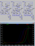
And here with a 3rd 2SA version that is very lightly compensate, phase max at 63deg (very good)
Attachments
What is the output impedance sim of the total reg for 70mA spare above load?
With a load of 50mA(dc) and 50mA(acpp) sinusoidal load variance (eg a load sinus of mA to 25mA(low) to 75mA(high)) the simulator gives a 31uVpp ripple. That should be equivalent to (in my reckoning) 31upp/50mpp = 620uOhm. But this is for a very unrealistic load (really worst case
). If this is what you wanted to know Energize the main voltage source for ACampl=1, also the load sink. Run an AC sweep on the output with the probe off .params prb=0 go click to the chart's left side and ask for logarithmic. What you see complies to Ohm scale too now. That way you can see what it does across wide band.
Also I do not think this is realistic, in real life, the PCB (layout and track resistances) is not modeled in there. SO this is why I never posted sim results like that
Jack had run the 1.1 on AP2 once and it was bang on to the sim and actually a bit better than the model for supersonic. It can be near if you will model the lines inductance and their resistance. Still 0.62mOhm strikes me as a bit optimistic for the limited Gfs a 9610/610 can have when shunting 50mA. Even on optimal local node.
Let’s see what happens when the RIAA is connected.
All quiet on that front. I just examined it up to the phono after doing the rails jumpers. No oscillations nowhere. The residual noise looks bumped up enough from when PSU alone is a difference. But now there is a multifaceted active load entering the picture we shall not forget. Or it has to do with the large loop area the all in one ground plane has. To remind, this is a fast TOSHIBA TO-220 BJTs build with NO 1uF capacitors bypassing the phono lytics but the 0.1uF cap across rails for the OPA is still there. 10uF PSU caps are Nippon KMQ. It also has 10K instead of 150K servo injections showing insignificant offset and -0.136VDC on OPA pin 6. Hfe is generally well near all over with lowest finds used in the CV/CCS part. IDSS of K170s used was around the 7mA mark. J310s just random.
To conclude my practical points feedback, I recommend 0.6mm solder wire because there is not much pad real estate and to finger touch them as little as possible. They tend to oxidize too fast. Had to use the flux pen often after a few days to revisit it although I used a 60W Metcal Iron and lead solder. I also consider a delay on-fast release off output relay a must if care free on/off DC offset cycles are needed. It peaks high DC on output during those cycles. Hope those clues can come handy to some folks.

- Home
- Source & Line
- Analogue Source
- Paradise Builders