Werner, many thanks for the praise - I really only did this for the fun! Glad to help.....
This also allowed me to go to the bottom of that input voltage issue - after adjusting, I wondered about my own boards (R2 beta, without input offset adjustment), only to find out that they have significant input offset ;-( And, the sound comparison then brought this to light, so in the process we all learned something...
This also allowed me to go to the bottom of that input voltage issue - after adjusting, I wondered about my own boards (R2 beta, without input offset adjustment), only to find out that they have significant input offset ;-( And, the sound comparison then brought this to light, so in the process we all learned something...
Werner, many thanks for the praise - I really only did this for the fun! Glad to help.....
This also allowed me to go to the bottom of that input voltage issue - after adjusting, I wondered about my own boards (R2 beta, without input offset adjustment), only to find out that they have significant input offset ;-( And, the sound comparison then brought this to light, so in the process we all learned something...
We say in Ireland " every day is a school day"
Take care
")
Werner
Folks
Alfred talks about my boards. You are remember my problems:
Originally Posted by hesener
Hi Werner, can you confirm that the input voltage (measured at the input pins) is +2.5V, and the output voltage is +15V? How about VCASCH and VCASCL, and the voltages across the 6800uF caps?
Hi Alfred, I have just measured (Fluke 787)
UPLUS = -18,13
UMINUS= +18,13
INPUT = +2,48
OUTPUT= +15,23
VCASCH= +14,49
VCASCL= -14,56
Across the 6800 uF caps plus side +1,73
Across the 6800 uF caps minus side -3.16
EXI RIAA= +15,23
Alfred ask me to send the boards over to him for a check and he found
that I have forgot to adjust THE INPUT OFFSET . My fault
it for me, measured all importend things, and told me that everything it
perfect now!!!
When I have the boards back in Ireland and Peters power supply is finished I will give same sound impressions.
Alfred thanks a million you do a grand job and thanks to all other lads for help
That was exactly what I measured after soldering. But I didnt care about "and let the Caps burn in". The caps got a kind of incontinence. My fault, but please learn from this
Caps dont like a negative voltage at the + pin. After adjusting the trimmer we should use a 10k R from input to ground, right. Some of us need some lower values, especially with high output MC´s, even right? And what about a load of 2,2 nF is it for everybody or only the high Outputters? could someone explain, please.
That 10 Ohm resistor is a dummy resistor that should be taken out after adjusting the input DC. I chose that value because most MC systems have a DC impedance between 2 and 40 Ohm.
You then can adjust the input impedance of the Paradise at will considering that the "natural" input impedance of the Paradise is 10kOhm so only values under that are possible. For example you use a 10kOhm resistor from input to ground. That would make the input impedance ca. 5kOhm. You can add parallel caps at will too but you have to look up the manufactures specs for the cartridge you use. This caps have no influence on the input offset.
The Paradise is made for low output MC systems. High output MCs are not really recommended although they could work if output is not too high ( up to 2mV is ok ) and surely no MMs.
oops, one small correction if I may JG: Please use a 10 Kiloohm resistor for adjusting the offset. If you put a 10 Ohm resistor, you will see nothing.... It is even possible to start the adjustment process without any input resistor, and when you arrived below +/- 100mV or so, then put in the 10kOhm and adjust the last remaining millivolts....
Everything else makes perfect sense. The system I use has a DC coil impedance of 30 Ohm, and really likes about 1000 Ohms
Everything else makes perfect sense. The system I use has a DC coil impedance of 30 Ohm, and really likes about 1000 Ohms
Yes, the lower the resistor, the lower the reading. Even with the "old" Paradise DC input offset was not REALLY a problem
ones the cartridge is connected.
I put in the offset trim because some here do not accept ANY offset, even in the uVolts.
The good think with this trim is that it also lowers distortion because differences in the emitter impedance are eroded. It is really a local differential feedback.
It has a double purpose, you know.
We have discussed this many times but i can understand that new comers do not read the whole thread and this is only one that has the Paradise as topic.
The best recommendation is to read the constant updated assembly guide ( thanks Alfred, this is a lot of work for you ).
If then a problems comes up the MPP team is more then willing to help.
The best recommendation is to read the constant updated assembly guide ( thanks Alfred, this is a lot of work for you ).
If then a problems comes up the MPP team is more then willing to help.
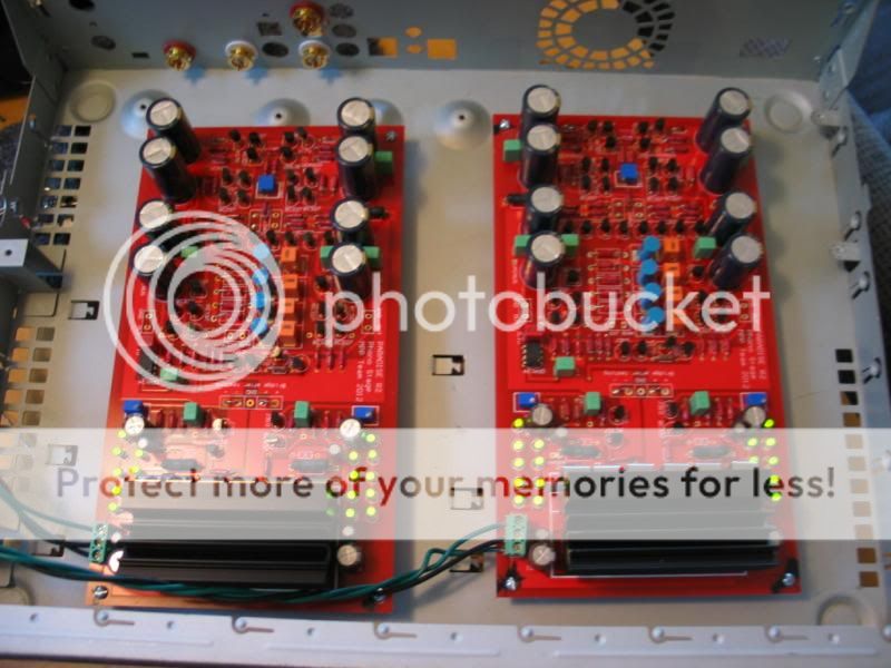
Finally back after sending my boards to a buddy for testing. Both boards exhibited the dreaded oscillations, but the reccomended caps worked perfect. Amplifiers were fine. Just fired them up and the PS is feeding them 36.2vdc. Voltage reads 18.1vdc, I let them run for 30 min and i can keep my fingers on the heat sinks but very warm.
Couldn't find my meat thermo for crude measure.
Is 36vdc gonna cause excessive heat? What would be the formula for reducing these a tad if necessary with resistors??
Thanks
Will give a listen tomorrow.
Couldn't find my meat thermo for crude measure.
Is 36vdc gonna cause excessive heat? What would be the formula for reducing these a tad if necessary with resistors??
Thanks
Will give a listen tomorrow.
Last edited:
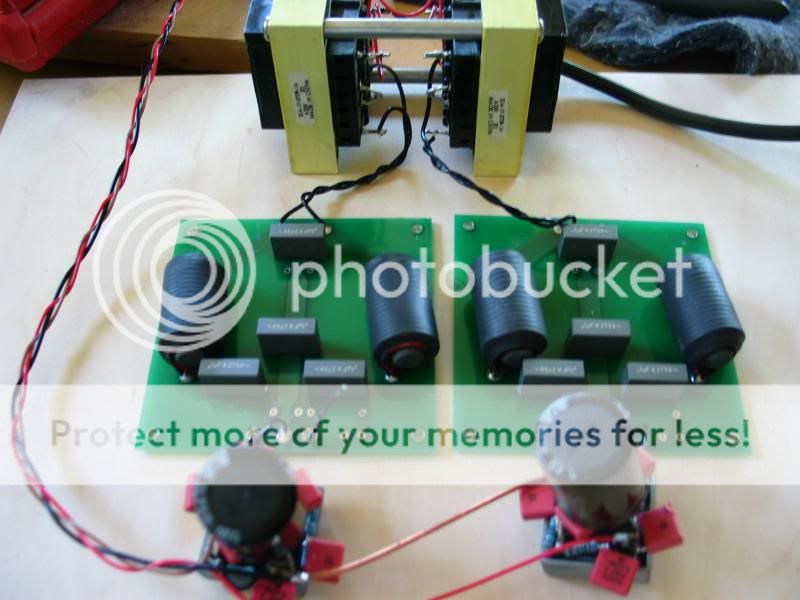
Measure the output voltage of your pre regulator without connecting the Paradise boards.
Then connect the Paradise boards and measure the voltage again.
How much drop do you get ? By Ohm´s law U = R x I you can dimension the drop resistor.
The wattage of the resistor can be found by the dropping voltage multiplied by the drawn current. U x I = Power in wattage. Dimension the wattage of the resistor at least two times that power or it will get quite hot although it will not burn.
Measure the output voltage of your pre regulator without connecting the Paradise boards.
Then connect the Paradise boards and measure the voltage again.
How much drop do you get ? By Ohm´s law U = R x I you can dimension the drop resistor.
The wattage of the resistor can be found by the dropping voltage multiplied by the drawn current. U x I = Power in wattage. Dimension the wattage of the resistor at least two times that power or it will get quite hot although it will not burn.
Measurement before board was 42vdc and with both boards connected 36.2 at boards. What should be my resistor?
thanks
I had a pair of 10ohm 5 watt resistors left over from my DCB1 build but it only bought me 3v reduction. I connected leads and its making music!! PTL
Resolution is up several notches and its quiet as mouse compared to my modded Cambridge.
Gotta order some larger value resistors to get voltage down and get some breakin done.
Very pleased with sonics so far. BIG thank you to all!!
Resolution is up several notches and its quiet as mouse compared to my modded Cambridge.
Gotta order some larger value resistors to get voltage down and get some breakin done.
Very pleased with sonics so far. BIG thank you to all!!
What about using a number of diodes instead of resistors, like C-D-C instead of C-R-C?
Not good, it (using diode(s)) will create switching artifacts/noise. At some point the 'input'-capacitor will have a lower voltage than the 'output'-capacitor and the current will switch off. (other way around is the same except 'on'
).Also when off the diode has a very high impedance, and when on the diode has a very low impedance, this is not good for the filter that you would like to have.
I had a pair of 10ohm 5 watt resistors left over from my DCB1 build but it only bought me 3v reduction. I connected leads and its making music!! PTL
Resolution is up several notches and its quiet as mouse compared to my modded Cambridge.
Gotta order some larger value resistors to get voltage down and get some breakin done.
Very pleased with sonics so far. BIG thank you to all!!
Good to see that it is all working now have fun Nick77
 oops sorry wrong 'smilie' lets use these one's


- Home
- Source & Line
- Analogue Source
- Paradise Builders