Dimitri,
that's interesting. I never came across that before.
Thanks a lot for clarification. Electronic cooling ...
sounds cool ;-)
Do you think R9 should still be connected to ground
now, or does it make sense now like it is?
In the formula of calculation of time constants it does't
seem to make a difference wether R9 is connected
to gound or to the Output of NJM4580.
I'd really like to have the original Actidamp schematic
to compare it to phonobox.
regards,
Stephan
An externally hosted image should be here but it was not working when we last tested it.
Bingo !
Dimitri discovered it - Marcel van de Gevel found the "Actidamp" principle about two years before me - but I can't his article (it was first published in Journal of Audio Engineering Society), so I found it independently.
The schematic shown below looks quite well - unfortunately the 2SK170 is out of production. But, it can be replaced by some switching JFET, e.g. 2N4393 - many of low level JFET switches having RDSON below 100 ohm are suitable, but they need to be selected into pair and tested for noise.
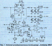
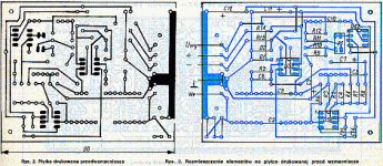
To Werner : It is schematic of my version active damping, amp named Actidamp IV. It was published in magazine Amatccaerske Radio cca eleven years ago. There is used " separed " all pasive correction - better explanation of function give you BOBOLIX, 'cos he is author of this principle.
Re: Bingo !
 I checked the Toshiba Web site, and there was no information that would make me believe that the 2SK170 is out of production. It is listed in the database and the latest datasheet is from May 2003.
Cheers
Tino
bobolix said:
unfortunately the 2SK170 is out of production.
I checked the Toshiba Web site, and there was no information that would make me believe that the 2SK170 is out of production. It is listed in the database and the latest datasheet is from May 2003.Cheers
Tino
Hi,
in the meantime i've swapped the op-amps in my
pro-ject phonobox:
TL061 => OPA134 (this is a FET Opamp used for Actidamp in
the phonobox)
NJM4580 => OPA2228 (this is the amplification part)
Also, i adjusted a number of resistors and capacitors,
as the phonobox (in some older revisions, including mine)
is somewhat inaccurate.
Pleas refer to the schematics here (thanks to Dimitri!!)
http://www.angelfire.com/az3/dimitri/images/phonobox.pdf
DO NOT connect R9 to ground as it is suggested in the PDF,
but leave it as it is. R9|| R8 = 5003,8 Ohm, together with
C6 gives 75,06 uS time constant !!
From talks to the developer of the original design I learned
that R9, C7 are not meant as a low-pass Filter, but this
is an optimasation noise-wise! My thanks go to Pavel in
czech republic!!
What I did exactly is :
R5 : 1,32 MOhm, was 1,2 MOhm
R6, R7 : 220kOhm , was 330 kOhm
C4 : 0,47 uF , was 0,33 uF
R8 : 5.6 kOhm (selected), was 4,7 kOhm
C7 : 10uF, was 2,2uF
C6 : 15nF (selected), was 18 nF
R10 : 300Ohm, was 270 Ohm
R11 : 2,7kOhm (selected) , was 2,7kOhm
R12 : 2,2kOhm (selected), was 2,2 kOhm
R13 : 47KOhm (selected), was 39 kOhm
C9 : 68nF (selected)
Also I bypassed all electrolytics with WIMA MKS2 capacitors,
approx. 0,33 uF, and replaced the ceramic capacitors
(100pF, 27 pF, 12pF) against better ones (Glimmer type,
sorry, I don't know the english word)
Altogether if gave a real boost to the phonobox, and in
comparisation to a Lehmann Black Cube the modified
phonobox does't made a bad figure in my setup at all!
In fact the results triggerd me to replace resistors /capacitors
in the Black Cube for better RIAA accuracy. It is much better
now, though all replaced parts were in their specified tolerance.
I have a unfortunate placemant of my speakers,
I am too far away from them, so my setup is very
sensitive to deviation between channels. My original
Black-Cube was alwasy somewhat out of center, after
replacing the parts it is 100% perfectly balaced!
I am getting the impression that maximum RIAA accuracy
it most imprtant to good sound. Use selected parts, try
to get better than 1 % tolerance to the CALCULATED
values. On resistors, you could use those (somewhat expensive) 0,1 % precision resistors. At the end, it doesn't cost
so much more compared to all the other efforts in an DIY project.
I do not think that the usage of "voodoo-parts" will
greaty improve the results.
Regards,
Stephan
As Jocko Homo told me in a different thread, some of the best Toshiba audio transistors are now being made "special order" with a minimum order quantity of 3000 pieces. This includes 2SK389 and maybe also 2SK170. They will disappear from the browsable product list but datasheets remain available.
I have a large overstock of 2SK170-BL. Email me if you're interested.
I have a large overstock of 2SK170-BL. Email me if you're interested.
dimitri said:>>From talks to the developer of the original design I learned
that R9, C7 are not meant as a low-pass Filter, but this
is an optimasation noise-wise!
Stephan, please, woud you like to explain this "noise-wise optimasation"?
Thank you
In fact, the lowpass of 75 us is created by complete circuit
consisting of R8, R9, C6, C7. The purpose of such complicated circuit is to achieve similar DC resistance "seen by" both non-inverting and inverting input of the following opamp and same time achieve low AC impedance of the low-pass, so that the noise introduced by the input current noise of the opamp would be reduced as well as the thermal voltage noise generated by the total resistance in the lowpass (R8 || R9).
>> In fact, the lowpass of 75 us is created by complete circuit consisting of R8, R9, C6, C7. The purpose of such complicated circuit is to achieve similar DC resistance "seen by" both non-inverting and inverting input of the following opamp and same time achieve low AC impedance of the low-pass, so that the noise introduced by the input current noise of the opamp would be reduced as well as the thermal voltage noise generated by the total resistance in the lowpass (R8 || R9).
Sorry Bohumil, I will interfere
1) yes, dc "seen by" both non-inverting and inverting input will be around 47k
2) > achieve low AC impedance of the low-pass - the output impedance of low-pass will be R8 4k7 with gradual decrease at hf. How R9 C7 will lower this? (R8 || R9) is only 10% reduction.
3) > the input current noise and thermal voltage noise - again, (R8 || R9) - 10% reduction is negligible.
4) dc shift of the input amp, worst case 5mV*28=140mV, will be presented at the output
Upupa Epops said:Guys, who will send me email, I will send him original schematic of Actidamp Mk II, not copy by Project. Questions ( if will be ) I can explain later.
it is me again,
please send me a sch if possible
Hi boys,
don't forget it is a construction about 20 years old. I learned something since then and now I'd make it different - frankly said, I did it so, but it has been made by an order and therefore it is a subject of the "bussiness secret". Though, I can say, the dc-servo path needs to be modified slightly at least ...
don't forget it is a construction about 20 years old. I learned something since then and now I'd make it different - frankly said, I did it so, but it has been made by an order and therefore it is a subject of the "bussiness secret". Though, I can say, the dc-servo path needs to be modified slightly at least ...
BTW...
... the Actidamp was made as an optimization for the MM pickup regarding noise. Recently the MCs are assumed to be the best usually and the Actidamp need not to be the optimum solution. E.g., the linear pre-preamp could be made as balanced using some of ICs determined for mic preamps - INA217 e.g. I've made even a fully symmetrical phono preamp, i.e. with completely symmetrical signal path including the equalization circs, but probably it will never be published.
... the Actidamp was made as an optimization for the MM pickup regarding noise. Recently the MCs are assumed to be the best usually and the Actidamp need not to be the optimum solution. E.g., the linear pre-preamp could be made as balanced using some of ICs determined for mic preamps - INA217 e.g. I've made even a fully symmetrical phono preamp, i.e. with completely symmetrical signal path including the equalization circs, but probably it will never be published.
- Status
- This old topic is closed. If you want to reopen this topic, contact a moderator using the "Report Post" button.
- Home
- Source & Line
- Analogue Source
- Schematic for Pro-ject phono box