My 2SK240/ECC88, 6SJ7 RIAA build
As a student, I made a PAS3X clone of the Dynaco preamplifier. A simple two stage ECC83 concept, with an added buffer stage (three ECC83 sections). It is conformant to the specs, with a warm hint in the lows.
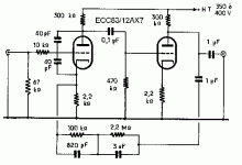
The difference we (actyually my friend Peter Sikorski) had was an added output buffer of ECC83.
I used it for a few years until I bought a Yamaha CA-1000.
Around 1982 I got a subscription on the French magazine L’Audiophile, with Jean Hiraga as editor. A great guy. I made one of his implementations of the Kaneda solid state preamplifier including an RIAA section. I also made his 8W Le Monstre, my version weighted more than 30 kg’s. And I made the Le PrePre. The preamp combo was great.
But after a few years I decided to go triode again. Just for fun. But what to do? I had Hiraga’s design for a tube RIAA (roughly based on a McIntosh C22) from September 1981, but :
To the drawing board!
I decided to start the first stage with a JFET and make a cascode with a triode. I had a pair of 2SK240 at hand, with a very high Gm, and an Idss of 2,5 mA.
[Note: One cannot use two 2SK170, for sheer high Idss of 8-10 mA! Two parallel means 15 mA through the triode, making the choice difficult, and making the anode load a nightmare. As well, they have a high 300-400pF input capacitance due to Miller effect and the high 2SK170 Ciss]
So I thought the ECC88 would handle the 5 mA well of a paralleled pair of one 2SK240. The anode load is a mu stage of this triode as well, not as SRPP. This in fact worked as a marvel on the breadboard. Although the amplification was not high, the the DC working points could be balanced implying at the same time that the output impedance would be changed too
  . That is bad for an attached filter, but on the other hand, the output impedance can be tweaked a bit.
[build note: ECC88 pins 6/7/8 is designed as the input of a cascoded triode; the pins 1/2/3/ are used for the top of the cascode. The filament/heater differs in the two sections.]
The 2SK240 - 6SJ7-based circuit
This was my first implementation with a 2SK240 at the input.
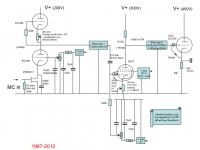
In a next post I will give more build details.
As a student, I made a PAS3X clone of the Dynaco preamplifier. A simple two stage ECC83 concept, with an added buffer stage (three ECC83 sections). It is conformant to the specs, with a warm hint in the lows.

The difference we (actyually my friend Peter Sikorski) had was an added output buffer of ECC83.
I used it for a few years until I bought a Yamaha CA-1000.
Around 1982 I got a subscription on the French magazine L’Audiophile, with Jean Hiraga as editor. A great guy. I made one of his implementations of the Kaneda solid state preamplifier including an RIAA section. I also made his 8W Le Monstre, my version weighted more than 30 kg’s. And I made the Le PrePre. The preamp combo was great.
But after a few years I decided to go triode again. Just for fun. But what to do? I had Hiraga’s design for a tube RIAA (roughly based on a McIntosh C22) from September 1981, but :
- I wanted to go non-feedback. In my reasoning, the vinyl noise (dust, ticks, scratches) gets smeared out by the feedback – and then becomes audible. I figured dust often is around 1 micrometer large and at the speed of turning it in general should be above 15-20 KHz – beyond perception.
- I wanted to go directly in with a MC element. So I needed more amplification than a standard tube design. I wanted to plug in my Ortofon low output MC directly.
- MC low input directly to line level in two amplification stages, not more implies it should provide at least 85-90 dB of amplification. This implies using a steep pentode if needed.
- To adapt the low level, an input silent JFET should be tried, but not as a separate stage. Rather as a cascode.
- I like to have the 2122 Hz as last filter section, because this way the noise floor of the second stage is reduced too.
To the drawing board!
I decided to start the first stage with a JFET and make a cascode with a triode. I had a pair of 2SK240 at hand, with a very high Gm, and an Idss of 2,5 mA.
[Note: One cannot use two 2SK170, for sheer high Idss of 8-10 mA! Two parallel means 15 mA through the triode, making the choice difficult, and making the anode load a nightmare. As well, they have a high 300-400pF input capacitance due to Miller effect and the high 2SK170 Ciss]
So I thought the ECC88 would handle the 5 mA well of a paralleled pair of one 2SK240. The anode load is a mu stage of this triode as well, not as SRPP. This in fact worked as a marvel on the breadboard. Although the amplification was not high, the the DC working points could be balanced
[build note: ECC88 pins 6/7/8 is designed as the input of a cascoded triode; the pins 1/2/3/ are used for the top of the cascode. The filament/heater differs in the two sections.]
The 2SK240 - 6SJ7-based circuit
This was my first implementation with a 2SK240 at the input.

In a next post I will give more build details.
Hybrid RIAA Design overview
The 2SK240 is a double low-noise FET. I had both FETS parallel per channel. Each has an Idss of 2,5 mA. The JFETS are directly connected to ground.
I took a small drain cap to catch any HF in the source.
The input resistance of 43 ohms is a Dale low inductive type.
I slightly raised the triode grid of the E88CC cascode section (grounded grid) a few volts (3) above ground. I used the + 12 Volts of a heater and a 7805 and some filter and trimmer.
The input circuit anode initially was an active SRPP stage, but I changed it later to a mu-stage because that way I can manage the output impedance better (trim to same both channels). This is feeding to the roll-off filter of the RIAA the 75μSec/2122 Hz filter section.
The second stage was to a steep amplification stage with a 6SJ7, a pentode that I had also used as first stage in a 10Y SET amplifier. To increase the gain I used a fixed bias, and just a small resistor (20 ohm potmeter) for balancing purpose. The 6SJ7 tube is so steep that I once saw sparks coming off the G2 pins at powering up – something I solved by adding 100 pF mica’s from G2 to K on the pins.
The anode load was made up of 2 times 2 parallel 47k resistors (Corning glass tin oxide metal film).
The bias of the 6SJ7 was based on four red LEDS in series (each 1,685 volts), filtered with a bank of solid tantale capacitors. This allowed me to set the Va slightly below the Vg2 of 120V (shunt supply using a 10W 120V zener).
After the pentode the RIAA 318μSec/500,5Hz-3180μSec/50,05Hz. I measured the output impedances of both stages (using the shunt method) and adapted the filter components.
And finally an output buffer with an ECC83. The output buffer has a forward biased diode to overcome start-up problems in the output tube (grid arcing) . Though the circuit shows a 50k cathode load, I quickly changed to an active load of the second half of the ECC83. (Some designers have used a neon instead of a diode. Might be sonically better!)
I used a separated PS box, starting from 550V (440V secondary rectified) that was outputting 400V DC with an active regulator. A bit overdone. The power supply had a 6336 as regulator tube for series regulation from the 400V to 300V. A bit big . . . But it worked.
I liked this hybrid RIAA – it works. MC low input directly to line level! Two amplification stages! Clear sound. Worked well for more than a decade.
In the past few years, I found similar designs from around 2000 of a FET/triode cascode input stage such as from OZLOESCH, using 3 paralleled FETS (2SK367) and later in 2001 Aquablue made a nice preamp with a OZloesch concept of a hybrid 2SK170/417A tube. Also take a look at A Loesch hybrid variation that discusses the use of DHT in this hybrid concept.
Next I'll discuss some improvements I made. I thought I could improve on the 6SJ7.
Last edited:
Second development step of my hybrid
My initial build had a double 2SK240/ECC88 cascode, then a 6SJ7 pentode.
Sounded good for years . . But
beginning 2010 I found that the sound slowly became less than I expected.
I tested the voltages and noted the input triodes were misaligned, one had 100 Va the other 30 Va and was drifting down slowly.
I rolled tubes,
Maybe the mu stage was at fault, so I changed it to a pure anode load. No improvement.
After a lot of tweaking and changing things that were not broken, I found out one of the 2SK240’s (a double FET) had gone mad. After a few minutes the Idss started to rise on both FETS of the pair, forcing the triode to conduct more and more. So I had to take that faulty thing out.
Is the hybrid cascode topology at fault?
No, the hybrid concept is very good. Silent. Fast. Low impedance.
I split the remaining 2SK240 pair over the two channels, consolidated the triode to a cascode with a 43K anode resistor. This however reduced the PSRR and increased in the background hum (power supply) a bit. It is now noticeable when there is no disc - it is at or just below the level of disc surface noise.
I also changed the output buffer of the first stage, an E88CC, as a cathode follower (Rk=13k ohms).
My 2SK240/ECC88, 6SL7 double cascode RIAA build
version 2 developed: the 6SL7 cascode-based second stage.
While I was at it, I also decided to replace the pentode and got me self a pair of 6SL7 triodes for a cascode. The 6SL7 as cascode is much steeper than the 6SJ7 pentode and has significantly lower noise floor.
I added a buffer after the 6SL7 cascode: an E88CC/E188CC cathode follower.
The sound improved a lot in transparency, better than the pentode.
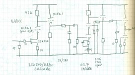
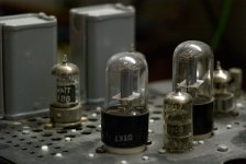
The top view:
My initial build had a double 2SK240/ECC88 cascode, then a 6SJ7 pentode.
Sounded good for years . . But
beginning 2010 I found that the sound slowly became less than I expected.
I tested the voltages and noted the input triodes were misaligned, one had 100 Va the other 30 Va and was drifting down slowly.
I rolled tubes,
Maybe the mu stage was at fault, so I changed it to a pure anode load. No improvement.
After a lot of tweaking and changing things that were not broken, I found out one of the 2SK240’s (a double FET) had gone mad. After a few minutes the Idss started to rise on both FETS of the pair, forcing the triode to conduct more and more. So I had to take that faulty thing out.
Is the hybrid cascode topology at fault?
No, the hybrid concept is very good. Silent. Fast. Low impedance.
I split the remaining 2SK240 pair over the two channels, consolidated the triode to a cascode with a 43K anode resistor. This however reduced the PSRR and increased in the background hum (power supply) a bit. It is now noticeable when there is no disc - it is at or just below the level of disc surface noise.
I also changed the output buffer of the first stage, an E88CC, as a cathode follower (Rk=13k ohms).
My 2SK240/ECC88, 6SL7 double cascode RIAA build
version 2 developed: the 6SL7 cascode-based second stage.
While I was at it, I also decided to replace the pentode and got me self a pair of 6SL7 triodes for a cascode. The 6SL7 as cascode is much steeper than the 6SJ7 pentode and has significantly lower noise floor.
I added a buffer after the 6SL7 cascode: an E88CC/E188CC cathode follower.
The sound improved a lot in transparency, better than the pentode.

The top view:

Some backgrounds
Additional background on the hybrid circuit:
see OZloesch hybrid RIAA 2SK369
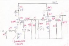
A nice circuit; and I see we developed some ideas in parallel. I also made a tube based shunt with a TL431 in the cathode lead.
Additional background on the hybrid circuit:
- See also Allen Wright’s RTP3B phono stage with a hybrid FET/tube input and a split EQ between Phono & Line Stages. He uses 2SK147, 2SK170 or 2SK369 Y or BL grade. His ECC88 anode load is 25K, Vb is 300V.
- John Broskie commented on the idea of a hybrid. Though he created a surprise for us (as always): he turned the hybrid input into a hybrid Loftin-White stage , one where the cathode is earthed (instead of the grid) : instead of a cascode where the second tube is grounded grida and the cathode floats with the input current; in the Loftin-White the cathode sees a fixed voltage reference and the tube gets a variable grid signal from the drain current of the jFET. An interesting idea.
- see the OZLOESCH. I have a downloaded design file (Moving Coil Phono Preamp-417) that disappeared from the WEB.
see OZloesch hybrid RIAA 2SK369

A nice circuit; and I see we developed some ideas in parallel. I also made a tube based shunt with a TL431 in the cathode lead.
Revisiting the circuit
Version 3, May 2012
The hybrid ECC88/6SL7cascode RIAA preamp left me to do some work again.
I made an inverse RIAA.
I quickly decided to improve the PS:
Version 3, May 2012
The hybrid ECC88/6SL7cascode RIAA preamp left me to do some work again.
- check the RIAA conformity with an anti-RIAA .
- check the performance again. In detail.
- remake the power supply. It has a lot of shot noise in the sub Herz region (I call it ‘power line flutter’).
- I hear some power line hum, maybe from the heaters.
I made an inverse RIAA.
I quickly decided to improve the PS:
- use a rectifier tube 5R4/GY instead of a rectifier bridge, excellent sonics also fit for low power stages (and high voltages, but that is not needed here). At HV a CL input cannot have mote than 4 uF with 560ohm total resistance of transformer plus choke; here at low voltages I have 50 ohms transformer, and LC with 1H choke 200 ohms and 10 uF. Good enough. No arcing.
I used two BY127 (max 1.400V) and connect these to earth from the hot terminals. This way I get a bridge. The influence of the solid state diodes is negligible; the tube completely dominates the transfer characteristics. - a choke loading: LCLC for the first stages, 1H/10uF, 7H/30uF
- I made a Salas Simplistic HV shunt
- I tested an OD3 as reference for the input stage as well as a EL84 based shunt
RIAA and its inverse
Comments about the RIAA filter.
Because I have a new preamp (SP-6 clone) that is very very ‘clear’ in it’s sound stage, I decided to review the values. My
new SP-6 Light showed some extreme dynamics, brightness, which might imply a small clarity (presence effect) in the vinyl reproduction.
It highLights a part of the spectrum = or it is just a bonus of the line amp.
The first filter section starts with an E88C buffer.
Ideal 2122 Hz filter from the online calculator: 47k3 and 1585 pF. A simple RC filter.
The actual filter, first stage 2122 Hz: Because the output of the cathode follower is about 300 ohms, I had 47k/1585 pF (measured 2010) . This filter section is loaded by an Rg of 1M in the 6SL7, ideally this would be 2M2 (50* as high) to not load the filter.
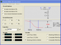
The second stage filter is a classic compound and starts with an E188CC buffer stage and again here the filter input compensates for this.
The ideal 50/500 filter values : R1 = 102k9 ; C1 = 27,8 nF; R2 = 11k43.
Implemented:
(as measured R/L)
For R1 a 100k 0,1% is used, but I understand this overestimates the output impedance of the ECC88 buffer (something like 300 ohms??).
2010 measurements R2 = 11k42 and C1 = 27,8 nF
2012 measurements: R2 = 11k39 and C1 = 28,12 nF
→ This implies the R1 values should be increased by a small fraction (2k6) and C1 is too high.
However, as with all measurements: what to trust? The second measurements are with improved 5 1/2 digit equipment, so is better ??.
Even testing with an inverse RIAA or anti-RIAA filter made based on actual measurements of component values implies I also there fall in the measurement trap.
Check and recheck: My new 5 digit cap meter is not consistent, my old 4 digit one is.
Comments about the RIAA filter.
Because I have a new preamp (SP-6 clone) that is very very ‘clear’ in it’s sound stage, I decided to review the values. My
new SP-6 Light showed some extreme dynamics, brightness, which might imply a small clarity (presence effect) in the vinyl reproduction.
It highLights a part of the spectrum = or it is just a bonus of the line amp.
The first filter section starts with an E88C buffer.
Ideal 2122 Hz filter from the online calculator: 47k3 and 1585 pF. A simple RC filter.
The actual filter, first stage 2122 Hz: Because the output of the cathode follower is about 300 ohms, I had 47k/1585 pF (measured 2010) . This filter section is loaded by an Rg of 1M in the 6SL7, ideally this would be 2M2 (50* as high) to not load the filter.

The second stage filter is a classic compound and starts with an E188CC buffer stage and again here the filter input compensates for this.
The ideal 50/500 filter values : R1 = 102k9 ; C1 = 27,8 nF; R2 = 11k43.
Implemented:
(as measured R/L)
For R1 a 100k 0,1% is used, but I understand this overestimates the output impedance of the ECC88 buffer (something like 300 ohms??).
2010 measurements R2 = 11k42 and C1 = 27,8 nF
2012 measurements: R2 = 11k39 and C1 = 28,12 nF
→ This implies the R1 values should be increased by a small fraction (2k6) and C1 is too high.
However, as with all measurements: what to trust? The second measurements are with improved 5 1/2 digit equipment, so is better ??.
Even testing with an inverse RIAA or anti-RIAA filter made based on actual measurements of component values implies I also there fall in the measurement trap.
Check and recheck: My new 5 digit cap meter is not consistent, my old 4 digit one is.
Inverse RIAA
The anti-RIAA circuit
To test the RIAA I have made an anti-RIAA circuit.
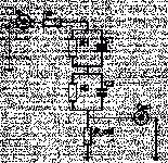
An inverse RIAA is used to test the response conformity as follows: a signal generator is connected to the input of the filter. The output of this filter is connected to the RIAA input.
A (manual) sweep in the generator will then have to result in a flat response at the end of the pick up pre-amplifier.
It can then be viewed on the scope and on a dB meter.
Of course one can simulate the actual built circuit, but I have no simulator software any more since I have a Mac .
.
Circuit changes:
Filter: While I was at it, I recalculated the whole circuit; measured the values of components, and found some deviations in the order of more than 0,5%. I decided I could do better and revised parts to less than 0,5%. I also added a fourth pole at 50 kHz.
2nd stage: I found out that when I loaded the preamp directly with my generator, at 1 mV in, that the second stage had little headroom, showed severe compression when stretched above 2 mV in.
This was the reason for the roll-off below 150 Hz: it just saturated at these enormous signal levels
Consequently I redesigned stage and discarded the cascode that had too little headroom - good in the listening room and actual signal levels but uneasy on the testbench. The newly dimensioned second stage is based on a SRPP and can output 30V RMS so it does not have any compression effects!
My inverse RIAA
I made two circuits; they theoretically deviate a little bit, in the order of 0,1 dB.
Lipshitz:
R3=0, R1=883k3 C1=3.6nF R2=75k C2=1nF Rload=604ohm. I use a trick: a potmeter for Rout, so I can set the total resistance to 604 ohms, including the input impedance of the MC input stage of 39 ohms. In fact this then resolves the correct loading when connected directly to the input of 39 ohms.
Hageman:
R3=1910 (I took 1k8 I had at hand); R1=511k C1=6.2nF R2=42k2 C2=1.8nF All except R3 within 1% measured. Load=series 536+60 ohm for -40 and -60dB test signals. I used a 560 ohm and used no extra resistor to earth; connected it directly to the 39 ohm input impedance of my FETS. This then should give the same impedance for the filter.
Background of these implementations, see, Ake Holm’s page on the inverse RIAA
Interesting is that you can see no filter is really 0,00 dB flat conform to the recording association’s standard. I note however, that paralleling two circuits like Holm’s my_filter1 and -2 would give a best implementation …
I choose the implementation by Lipshitz and refined this after looking at
the original article he wrote.
Also interesting is a
recalculated circuit by Hagerman (p5) that has a wider bandwidth than Lipshitz.
The anti-RIAA circuit
To test the RIAA I have made an anti-RIAA circuit.

An inverse RIAA is used to test the response conformity as follows: a signal generator is connected to the input of the filter. The output of this filter is connected to the RIAA input.
A (manual) sweep in the generator will then have to result in a flat response at the end of the pick up pre-amplifier.
It can then be viewed on the scope and on a dB meter.
Of course one can simulate the actual built circuit, but I have no simulator software any more since I have a Mac
- The circuit showed a misalignment of 0,3 dB at 20KHz.
- from the articles by Hagermann I concluded I wanted to add the fourth pole that sits at 50 kHz, as advised by Hagerman.
- The circuit also showed a severe roll-off below 150 Hz. This evidently is an artifact I could not explain, as the equalizer is well-calculated and coupling caps are rightly dimensioned.
Circuit changes:
Filter: While I was at it, I recalculated the whole circuit; measured the values of components, and found some deviations in the order of more than 0,5%. I decided I could do better and revised parts to less than 0,5%. I also added a fourth pole at 50 kHz.
2nd stage: I found out that when I loaded the preamp directly with my generator, at 1 mV in, that the second stage had little headroom, showed severe compression when stretched above 2 mV in.
This was the reason for the roll-off below 150 Hz: it just saturated at these enormous signal levels
Consequently I redesigned stage and discarded the cascode that had too little headroom - good in the listening room and actual signal levels but uneasy on the testbench. The newly dimensioned second stage is based on a SRPP and can output 30V RMS so it does not have any compression effects!
My inverse RIAA
I made two circuits; they theoretically deviate a little bit, in the order of 0,1 dB.
Lipshitz:
R3=0, R1=883k3 C1=3.6nF R2=75k C2=1nF Rload=604ohm. I use a trick: a potmeter for Rout, so I can set the total resistance to 604 ohms, including the input impedance of the MC input stage of 39 ohms. In fact this then resolves the correct loading when connected directly to the input of 39 ohms.
Hageman:
R3=1910 (I took 1k8 I had at hand); R1=511k C1=6.2nF R2=42k2 C2=1.8nF All except R3 within 1% measured. Load=series 536+60 ohm for -40 and -60dB test signals. I used a 560 ohm and used no extra resistor to earth; connected it directly to the 39 ohm input impedance of my FETS. This then should give the same impedance for the filter.
Background of these implementations, see, Ake Holm’s page on the inverse RIAA
Interesting is that you can see no filter is really 0,00 dB flat conform to the recording association’s standard. I note however, that paralleling two circuits like Holm’s my_filter1 and -2 would give a best implementation …
I choose the implementation by Lipshitz and refined this after looking at
the original article he wrote.
Also interesting is a
recalculated circuit by Hagerman (p5) that has a wider bandwidth than Lipshitz.
Revisiting the two stages of the circuit
The two stages of the circuit
The first stage amplifies 57 dB. Read it again: Fifty seven. I increased the source resistor from 1R8 to 10R and this dropped the amplification with 1,8 dB to 55dB. Maximum output of this stage is more than 10 volt RMS.
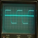
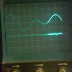
This picture shows the output of the first stage (2SK240, ECC88 cascode) of some 21V RMS , at 3 mV in from the generator. The solid line in the middle is the reactance of the Salas shunt that was dedicated to feeding the first stage and its buffer; this trace is at 2 mV/cm.
It shows the excellent overdrive capability of the first stage.
The second SRPP stage with 6SL7 amplifies another 30 dB. This brings the sensitivity for 1 volt RMS out (0,7 V RMS is nominal 0 dB) to slightly better than 0,5 mV from a MC cartridge. Two stages from MC to line level, plus two cathode follower buffers. It works. Like a charm.
I have a low output MC element, the MC30 from Ortofon with 0,2 mV at 1000 Hz. It manages that well, full dynamics.
This circuit is a little bit low in output level, maybe 6-10 dB below 0 dB line level, so I have to turn the volume up further. But it is manageable; it is slightly better than my DAC output.
The two stages of the circuit
The first stage amplifies 57 dB. Read it again: Fifty seven. I increased the source resistor from 1R8 to 10R and this dropped the amplification with 1,8 dB to 55dB. Maximum output of this stage is more than 10 volt RMS.

This picture shows the output of the first stage (2SK240, ECC88 cascode) of some 21V RMS , at 3 mV in from the generator. The solid line in the middle is the reactance of the Salas shunt that was dedicated to feeding the first stage and its buffer; this trace is at 2 mV/cm.
It shows the excellent overdrive capability of the first stage.
The second SRPP stage with 6SL7 amplifies another 30 dB. This brings the sensitivity for 1 volt RMS out (0,7 V RMS is nominal 0 dB) to slightly better than 0,5 mV from a MC cartridge. Two stages from MC to line level, plus two cathode follower buffers. It works. Like a charm.
I have a low output MC element, the MC30 from Ortofon with 0,2 mV at 1000 Hz. It manages that well, full dynamics.
This circuit is a little bit low in output level, maybe 6-10 dB below 0 dB line level, so I have to turn the volume up further. But it is manageable; it is slightly better than my DAC output.
Power supplies
Choke loading:
I chose a choke loading; with a 5R4 rectifier tube. My transformer is 318Volts AC, and after the 50 V drop of the rectifier and the LCLC, I still have 300V left with a 1,75 H first choke. With a load of 50-6- mA this however starts to drop to 250-240V. A bigger choke has better regulation but higher resistance, so the drop is higher.
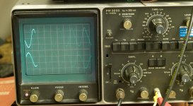
Note the good ripple reduction of the rectifier: no peaks, pure 50 Hz that can be regulated very well. Top 1st cell, bottom second:
Salas shunt
My SSHV: Made on a small perforated board. I use a 2SK585 for the current source, and because of the odd specs (-5V instead of -4V of the IRF6910) and other red LEDS I had to use 5 LEDS for a total of 7+ volts and a bias resistor of 68 ohm for a BIAS of roughly 56 mA.
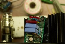
A 2SK170 with 500 ohm into a 100K wirewound resistor.
I used an IRFIB5n65a N channel 650 V mosfet for the shunt.
No signal and Salas with signal 500 Hz, 6 V pp:
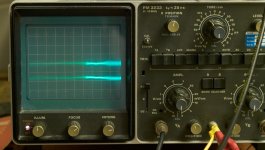
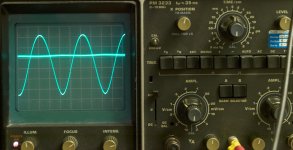
Very good in fact!
After some time however my SSHV1 suffered from severe low level sub-Hz line fluctuations (low PSRR, the same problem I had in my old supply). Well I discussed this a long time in Salas’s thread.
For the moment I am not using it.
OD3
The OD3 regulator tube surprised me with its low noise and absolutely perfect regulation from the pernicious sub-Herz line changes. It outputs 153 V at 10mA bias.
The tube shows some high frequency noise (above the audible band) of 2 mV RMS. This can reduced with a small cap of 200-300 pF but not too much. Top trace EL84 shunt 50 mV/cm directly on the last cell; bottom OD3 5 mV/cm. No line residue.
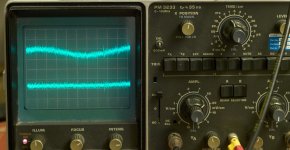
I tried the OD3 tube as reference: with an EL84 as buffer, the grid connected via a low pass 330k/0,47 uF capacitor: noise as good as the Salas SSHV; and regulation equally as good, and low noise is what counts. I decided to test this for the first stage.
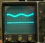
The advantage: the EL84 takes several seconds to warm up, so the first stage tubes are warmed up before they are fired up.
However, the 158 volts it delivers (OD3+EL84) is too little for the first stage; I designed it for 200 V! Otherwise I loose amplification.
EL84 and TL431 regulator
I have made several versions the past years that worked well and were stable. This one is with 750 ohms input as current limiter. Bottom trace previous cell, top is the output trace. The noise frequency is quite a bit higher than the OD3 has.
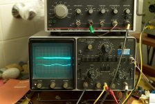
The Salas however outperformed this version with ease in low noise.
Heater circuits
I use a DC heater for all stages.
Power supply version 4, May 15
At the end I dropped this Salas shunt stage and reverted to a power supply with an EL84 as shunt. The Salas was good in the beginning but later became unstable. This is what happened on my SSHV1:
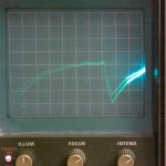
New PS components: Tube reg 5R4, 7H, 4uF, then I have a 750 ohms dropper resistor, then a EL84/TL431 shunt with 30 uF MKP, at this point there is 30 mV 50Hz and no low frequency drifts. Noise floor is hardly visible on 2 mV/cm.
Subsequently a source follower with a power FET with low-pass filter 220k/4 uF in the gate circuit, loaded with 4 uF and a 220 uF electrolytic on the output. All stages have a decoupling with a capacitor (4 to 5 uF MKP, with 5 ohms in series).
The Salas at 200V has a better defined space but I could for some reason not get that stable.
Choke loading:
I chose a choke loading; with a 5R4 rectifier tube. My transformer is 318Volts AC, and after the 50 V drop of the rectifier and the LCLC, I still have 300V left with a 1,75 H first choke. With a load of 50-6- mA this however starts to drop to 250-240V. A bigger choke has better regulation but higher resistance, so the drop is higher.
Note the good ripple reduction of the rectifier: no peaks, pure 50 Hz that can be regulated very well. Top 1st cell, bottom second:

Salas shunt
My SSHV: Made on a small perforated board. I use a 2SK585 for the current source, and because of the odd specs (-5V instead of -4V of the IRF6910) and other red LEDS I had to use 5 LEDS for a total of 7+ volts and a bias resistor of 68 ohm for a BIAS of roughly 56 mA.

A 2SK170 with 500 ohm into a 100K wirewound resistor.
I used an IRFIB5n65a N channel 650 V mosfet for the shunt.
No signal and Salas with signal 500 Hz, 6 V pp:


Very good in fact!
After some time however my SSHV1 suffered from severe low level sub-Hz line fluctuations (low PSRR, the same problem I had in my old supply). Well I discussed this a long time in Salas’s thread.
For the moment I am not using it.
OD3
The OD3 regulator tube surprised me with its low noise and absolutely perfect regulation from the pernicious sub-Herz line changes. It outputs 153 V at 10mA bias.
The tube shows some high frequency noise (above the audible band) of 2 mV RMS. This can reduced with a small cap of 200-300 pF but not too much. Top trace EL84 shunt 50 mV/cm directly on the last cell; bottom OD3 5 mV/cm. No line residue.

I tried the OD3 tube as reference: with an EL84 as buffer, the grid connected via a low pass 330k/0,47 uF capacitor: noise as good as the Salas SSHV; and regulation equally as good, and low noise is what counts. I decided to test this for the first stage.

The advantage: the EL84 takes several seconds to warm up, so the first stage tubes are warmed up before they are fired up.
However, the 158 volts it delivers (OD3+EL84) is too little for the first stage; I designed it for 200 V! Otherwise I loose amplification.
EL84 and TL431 regulator
I have made several versions the past years that worked well and were stable. This one is with 750 ohms input as current limiter. Bottom trace previous cell, top is the output trace. The noise frequency is quite a bit higher than the OD3 has.

The Salas however outperformed this version with ease in low noise.
Heater circuits
I use a DC heater for all stages.
- an IRF250FET that provides 12V (tubes as series pairs) from 16 V raw.
Connect the gate via a 10k resistor to a 220 uF capacitor - that provides 15,8V at the gate- just enough positive bias of 3,8V to get the needed 12,0 V output at 1 amp. This regulates like a charm, only some 50 Hz left (10 mV pp).
Another nice thing about this passive regulation heater circuit is that it has a very nice slow start – I use this slow start like a capacitance multiplier too for the - first stage, DC 6V with a darlington.
- 6SL6 with a combo of a shunt and a start-up current limiter.
Power supply version 4, May 15
At the end I dropped this Salas shunt stage and reverted to a power supply with an EL84 as shunt. The Salas was good in the beginning but later became unstable. This is what happened on my SSHV1:

New PS components: Tube reg 5R4, 7H, 4uF, then I have a 750 ohms dropper resistor, then a EL84/TL431 shunt with 30 uF MKP, at this point there is 30 mV 50Hz and no low frequency drifts. Noise floor is hardly visible on 2 mV/cm.

Subsequently a source follower with a power FET with low-pass filter 220k/4 uF in the gate circuit, loaded with 4 uF and a 220 uF electrolytic on the output. All stages have a decoupling with a capacitor (4 to 5 uF MKP, with 5 ohms in series).
The Salas at 200V has a better defined space but I could for some reason not get that stable.
Last edited:
Innovative??
A RIAA prototype from 1986:
I like to share some absurd idea.
I noted that having passive RC for the filter costs a lot of amplification: it is subtractive. So couldn’t this be done smarter? I decided: yes. I changed things around to get a partial decoupling on the cathode of a tube. After some testing, it indeed seemed to work.
The trick is the second stage, where the cathode is partially decoupled.
An initial wild idea, with the 50/500 Hz in the cathode load:
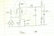
The second charcoal sketch (on brown paper) aligns the filters before and after the central second stage. It has a White Cathode Follower on the output definitely able to provide a low impedance to the interconnect:
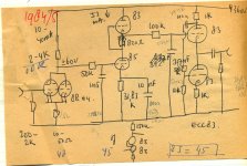
I implemented this idea a few years later.
My final breadboard version,
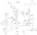
The impedances were adapted to the Rout of the preceding stage: so 50k and 318,3k were lowered. I measured the output impedances of the two stages.
However, I never took this to my listening room for long.
Several reasons:
It is the deterioration that made it unacceptable as I started to use E88CC and E801S tubes. Not el cheapo[/].
I saw the performance decrease on the scope, not in the room. A friend Eelco G. used it for some time and liked it well. And he has good ears.
In a similar vein of rethinking the obvious I also found
an RIAA design by John Broskie from 2002 where he also splits up the filter sections. He writes: “We can rearrange the sequence of the sub-networks so that the low-pass filter is tuned to 50 Hz and the shelving network applies to frequencies between 500 Hz and 2122 Hz, but this time the shelving boosts higher frequencies rather than attenuating them.”
Benefits and concerns he notes:
This implies my circuit idea is good . . .
Maybe I will revisit it.
A RIAA prototype from 1986:
I like to share some absurd idea.
I noted that having passive RC for the filter costs a lot of amplification: it is subtractive. So couldn’t this be done smarter? I decided: yes. I changed things around to get a partial decoupling on the cathode of a tube. After some testing, it indeed seemed to work.
The trick is the second stage, where the cathode is partially decoupled.
An initial wild idea, with the 50/500 Hz in the cathode load:

The second charcoal sketch (on brown paper) aligns the filters before and after the central second stage. It has a White Cathode Follower on the output definitely able to provide a low impedance to the interconnect:

I implemented this idea a few years later.
My final breadboard version,

The impedances were adapted to the Rout of the preceding stage: so 50k and 318,3k were lowered. I measured the output impedances of the two stages.
However, I never took this to my listening room for long.
Several reasons:
- the tubes deteriorated fast, even after 5 hours the amplification changed, and hence the filter values!!! There was a HF roll-off that was homing in from above 25.000 Hz, reaching 20 KHz and getting lower even.
Later I found out that probably I should have used diodes from grid to cathode to guard the triodes from becoming a shortcut across the grid at warm-up. I have drawn in the diodes now that I should have used. - well, I had both amplifier stages with its own power supply, tube rectified, separate per channel. That makes 4 power supply circuits, each its own rectifier tube. And I had a shunt reducing the HV from 250 V to 120 V with a zener.
- the transformers were old types that get hot on ‘modern’ 230V mains (made for 220V)
- it needed a MC stage input; and I wanted to combine it
- Wow. That became a heater installation by itself. Not good for long listening hours.
It is the deterioration that made it unacceptable as I started to use E88CC and E801S tubes. Not el cheapo[/].
I saw the performance decrease on the scope, not in the room. A friend Eelco G. used it for some time and liked it well. And he has good ears.
In a similar vein of rethinking the obvious I also found
an RIAA design by John Broskie from 2002 where he also splits up the filter sections. He writes: “We can rearrange the sequence of the sub-networks so that the low-pass filter is tuned to 50 Hz and the shelving network applies to frequencies between 500 Hz and 2122 Hz, but this time the shelving boosts higher frequencies rather than attenuating them.”
Benefits and concerns he notes:
- the 50Hz low-pass filter can filter more power supply noise away from the output signal than the 2122Hz can
- the 500Hz to 2122Hz shelving network can be implemented within one grounded-cathode amplifier, i.e. a single triode RIAA equalized preamp. Now if the bypass capacitor's value is reduced greatly, it introduces a shelving function, wherein the high-frequency gain is greater than the low-frequency gain, with the ratio being equal to the bypassed gain over the unbypassed gain
- He says the -12dB insertion loss is beyond the expected losses, which brings it 1kHz insertion loss down to -32dB.
This implies my circuit idea is good . . .
Maybe I will revisit it.
Nice presentation. Uncool that your take with alternative parts reg gave weird trouble. Maybe an SSHV2 try out with standard designated parts and layout at some point.
Thanks.
Yes, I try to use what I have on hand. Use things unspecified. Try out. Burn my fingers. Get blisters on my soul.
Of course I will definitely follow up. I liked the SSHV1 too much. Such a depth of sound.
But the detoriation of the performance has some source or reason and I hope I will uncover it. I ordered a batch (20) of MJE350's . . . and I plan use a socket to replace the jFETS.
Maybe . .
It might have to do with the very low capacitance of my lab supply. This goes off in less than a second. The reference cap then cannot bleed in time.
albert
I think this is the issue too. Though the added zener across the 2SK170 is a good idea.
And it explains why - when I change the supply voltage - the shunt performance drops in a different cycle.
And note that I did have a 220 uF cap in the load at one time too. Testing the waters.
 ).
).
But I won't give up. I'll make a new one from scratch.
Best is indeed use a fixed resistor in the source once I know the value: safest. Just trust the outcome.
And it explains why - when I change the supply voltage - the shunt performance drops in a different cycle.
And note that I did have a 220 uF cap in the load at one time too. Testing the waters.
(You might know the shunt that Guy Marec designed based on a classic error amplifier, he loaded it with 100.000 uF, even 220.000 uF to test it. With higher capacitance, the performance increased. )
Of course when I yank the supply up and then down or change the source resistance to set the output, the shunt gets a lot of work to do. (yanking, like yankees like to do, like apes like to do, yanking is making big leaps like dumbo's such as me do
 ).
). But I won't give up. I'll make a new one from scratch.
Best is indeed use a fixed resistor in the source once I know the value: safest. Just trust the outcome.
I used an inverse-RIAA (actually two, just to have double confirmation), this gives a nice capability to use a sweep.
I also used individual frequencies to check (like 20 kHz). Problem then is that the generator output meter is crude (two ranges KHz and MHz). So a 1000 Hz reference can be off a little bit.
But both ways I got a 0,3 dB too high at 20 KHz.
The sweep helped me find out that the second stage was quickly overloaded with low frequencies.
At this moment I am implementing two EAR843 circuits (from PCB's: one Zerozone, the other Zhilly - rather silly I do it twice?) in fact to have a reference for any change I make.
I will implement the same MC front-end, and am now simulating it.
I the mean time I have read all Broskies info on PSRR and he writes about my original circuit that using teh FET/ECC83 as a cascode reduces all PSRR to less than 1. So even a very silent power supply will have a signature.
And that is indeed the biggest remark I have for the current RIAA (2SK240-ECC88 cascode) I have. Fully open and some way beyond the surface noise I hear the net mains haberdashy.
However I found also an advise how to circumvent that. A Loftin-White circuit is suggested instead of the cascode, that will give better PSRR and Broskie. An alternative is to feed the top of the cascode with an extract of the PS to eliminate the last standing mains noise.
I am now modelling the EAR834 with that Loftin-White. I will post my simulations. Already saw that the EAR834 has poor HF (early fall off) and I think I found a way to prevent that (in LT Spice that is) without changing the basic circuit.
Just fun.
albert
Here is the first sim, EAR with stock components just against an anti-RIAA that I found uder the name of ElCheapo. The EAR834 part is from Hans Polak.
The main part is within 0,1 dB with a low bump of 0.7 dB at 20 Hz and a 20 kHz of -1 db.
Pretty unflattering.
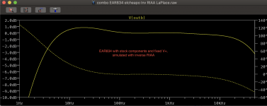
Next I will try to get this more straight and then add the FET.
The main part is within 0,1 dB with a low bump of 0.7 dB at 20 Hz and a 20 kHz of -1 db.
Pretty unflattering.

Next I will try to get this more straight and then add the FET.
Last edited:
- Status
- This old topic is closed. If you want to reopen this topic, contact a moderator using the "Report Post" button.
- Home
- Source & Line
- Analogue Source
- A two-stage MC tube based RIAA circuit