Spent an evening working on replacing all the electrolytic capacitors in my L-220 and noticing the improvement in sound (only minor, but a big reduction in audible noise) it got me thinking whether there were any improvements that i could make to the phono stage, like a better op-amp for instance. (i realise an external stage would be vastly better, but i would prefer to keep the internal one due to space and input limitations)
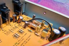
Phono Stage
The rest of the amp
I can post up schematics of the phono stage, the specs on the original NJM op-amp and component values if it helps. The cartridge i'm using with this is a shure M75ED T2 with jico SAS. (only other cart i'm likely to use is an AT30 MC via an AT630 transformer) The turntable i use is a Thorens TD160B with SME 3009S2 improved.
Phono Stage
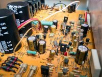
The rest of the amp
I can post up schematics of the phono stage, the specs on the original NJM op-amp and component values if it helps. The cartridge i'm using with this is a shure M75ED T2 with jico SAS. (only other cart i'm likely to use is an AT30 MC via an AT630 transformer) The turntable i use is a Thorens TD160B with SME 3009S2 improved.
Attachments
Last edited by a moderator:
Found this thread that so far is the only pointer i have for upgrading the original NJM2043D op-amp.
The current setup with the 2043 i find to be slightly bright, but due to a lack of experience with swapping out op-amps i am unsure what is the best solution.
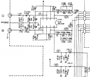
This is the phono stage section of the schematic.
The NJM2043 is roughly equivalent to a National LM833. Its strength is its OK bandwidth and noise, and a very low price.
For the phono stage, the AD712 seems like a poor choice because of its limited GBW and high voltage noise. Either the Burr-Brown OPA2228 or Linear Technology LT1126 should be a good choice. They're both low noise, decompensated bipolar op amps with good GBW and modest current demand. The LT1126 is faster but requires higher closed loop gains for stability.
The current setup with the 2043 i find to be slightly bright, but due to a lack of experience with swapping out op-amps i am unsure what is the best solution.
This is the phono stage section of the schematic.
Attachments
Last edited:
i find to be slightly bright
I'm not surprised; the unit does not have switchable input capacitors (cartridge loading) but sticks with the ubiquitous 100pF. Depending on your phono leads that might not be enough.
see Shure docs ('optimum load'):
http://es.shure.com/idc/groups/public/documents/webcontent/us_pro_m75edt2_ug_27a910(oh).pdf
This cartridge appears to need 400-500pF while the amp comes only with 100pF (+another 100pF from the phono leads or so). Increasing this capacitance will remove the brightness as it dampens the high frequencies.
The first and biggest improvement would be to add sockets (IC-socket pins for example) to allow using the proper capacitance recommended for your cartridge. One way to achieve this is by unsoldering the 100pF caps and use the holes for the sockets. If you do not intend to use any other cartridge you can also simply replace the 100pF with the proper value of about 300pF.
Then you can think about other improvements.
Enjoy, Hannes
Personally, I would not bother with fine details of the circuit at all; after modding it for switchable loading the next candidate would be the opamp itself.
Working on the fine details like the power supply is IMHO not really changing things. This is, after all, a very simple single opamp phono stage. Any decent opamp has in any case huge PSRR.
The NJM2043 is a bipolar opamp (stable for gains greater 20dB) with 14MHz and 6V/us slew rate, running at 18V rails in a dual package. I would try a OPA2134 (check pins!). You can also read the Analog addicts phono stage and the comments on suitable opamps there, it is roughly similar in concept.
http://www.diyaudio.com/forums/anal...-addicts-phono-preamplifier-2006-edition.html
Hannes
EDIT:
100pF/m is a common value, so this should be right.
Working on the fine details like the power supply is IMHO not really changing things. This is, after all, a very simple single opamp phono stage. Any decent opamp has in any case huge PSRR.
The NJM2043 is a bipolar opamp (stable for gains greater 20dB) with 14MHz and 6V/us slew rate, running at 18V rails in a dual package. I would try a OPA2134 (check pins!). You can also read the Analog addicts phono stage and the comments on suitable opamps there, it is roughly similar in concept.
http://www.diyaudio.com/forums/anal...-addicts-phono-preamplifier-2006-edition.html
Hannes
EDIT:
I believe is 130pF
100pF/m is a common value, so this should be right.
Last edited:
So i need to replace c101a/b with approximately 300pF for it to suit the shure. Should replace these with polystyrene like the existing ones or something like silver mica? (which seem to be easier to get hold of)
The pin config on the OPA2134 seems to match the NJM2043 in DIP-8 form.
The pin config on the OPA2134 seems to match the NJM2043 in DIP-8 form.
The L-430 should have an NJM4556 which is similar. Hoping to sort the opamp out soon. In the meantime i've been advised that I might get away with removing c104a/b and replacing the gaps with jumpers with the small possibility of cartridge dc leakage. Also swapping C103a/b for film replacements may gain a small improvement. (That is if i can find any in 22uF value that will fit, they are elna silmic II at the moment)
I've also been looking into swapping all the original carbon resistors for metal film. (the whole amp) Is there any disadvantage to using 0.5W over the original 0.25W and fitting them like this... (0.25W takman metal films cost nearly twice as much as 0.5W holco)
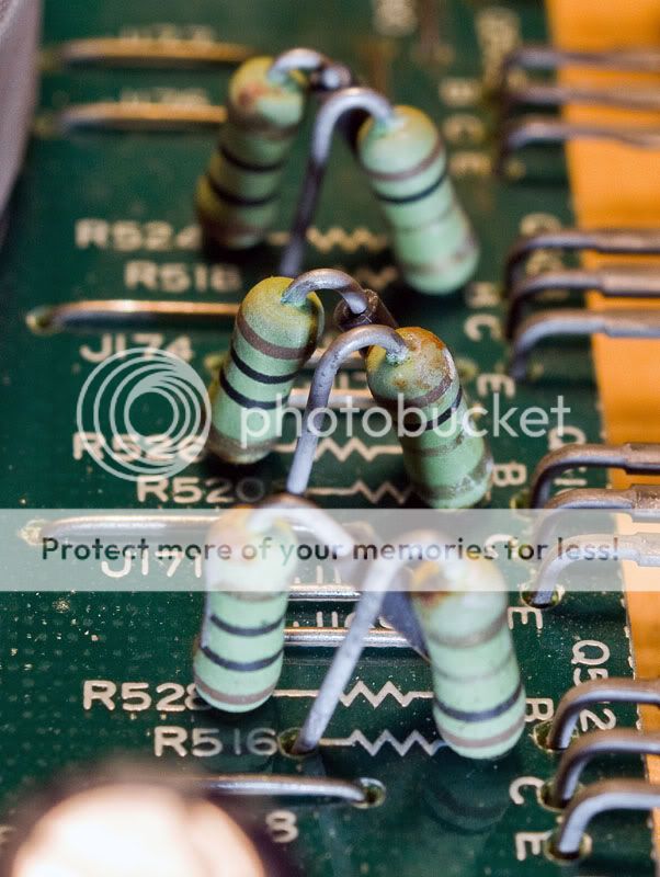
I've also been looking into swapping all the original carbon resistors for metal film. (the whole amp) Is there any disadvantage to using 0.5W over the original 0.25W and fitting them like this... (0.25W takman metal films cost nearly twice as much as 0.5W holco)
The picture above with the pale green resistors was an example of fitting. (picture is of an alpine car amp) I was just checking if fitting them like that in the luxman would be ok as they are presently fitted flat to the pcb. (if i went with the 0.5W replacements, they'd be too long to fit like they are and i'd have to fit them like that picture)
I've gone over the service manual and there are 91 carbon resistors (Rd in the manual) that i could swap for metal film. This does include the power circuitry as well as signal path. I actually don't know if i'd hear a difference or not, but i've read a few sources stating that metal film resistors have better noise characteristics. (i am a bit of a sceptic, but i like something to do of an evening)
I've gone over the service manual and there are 91 carbon resistors (Rd in the manual) that i could swap for metal film. This does include the power circuitry as well as signal path. I actually don't know if i'd hear a difference or not, but i've read a few sources stating that metal film resistors have better noise characteristics. (i am a bit of a sceptic, but i like something to do of an evening)
I understand you...
fitting resistors vertically has a couple of problems. They might be more prone to stray noise pickup. Lying horizontally puts them in closer proximity to the lower impedance tracks on the PCB where there will be less noise.
The noise level itself from carbon vs metal is probably not going to make any audible or measurable difference. That's because the circuitry is not designed from the outset to achieve lowest noise levels. You would be chasing fractions of a db.
The only exceptions I would consider to this are any high value resistors (say 47K and over) in the phono amp stage and any feedback resistors.
Also if you fit them vertically it will look awful imo. If you do go ahead and fit any vertically then make sure that the end with the longest wire to the PCB is at the low impedance point of the circuit to minimise the stray noise pickup.
I would recommend replacing any electroylitics though... which I think you have done.
Cheers for the advice. I'll have a measure of the existing resistors this morning to see if they will fit flat. I know that replacing the lot would be overkill so i'm going to look at just doing signal path only.
The electrolytics that are still original are the large psu filtration caps (which i will be replacing come pay day), there are 4 on the tone control & 2 on the function switch. I've also been looking at parts to replace the mylar/ceramic signal path caps with polystyrene/polypropylene too.
The electrolytics that are still original are the large psu filtration caps (which i will be replacing come pay day), there are 4 on the tone control & 2 on the function switch. I've also been looking at parts to replace the mylar/ceramic signal path caps with polystyrene/polypropylene too.
Ceramic caps in the audio path could be worth looking at.
From your diagram of the phono stage I would only look at replacing R102/103/105 with better. And certainly if you can not get these flat on the PCB then leave the originals fitted.
I think you will find the opamp will make far far more difference sonically than all the other mods you can do.
Good advice from Gary and well woth experimenting with different loading for the cartridge. Maybe even tweak the values on the PCB.
Yes that makes sense, will see what i've got and give it a go. I'd been told that the jico stylus that i've got on the shure doesn't need the recommended 4-500pF, but varying the cable length is a fair bit easier than soldering in different capacitors. (and allows me to experiment and find what sounds best for me)
There is one particular ceramic cap (C123a/b just above the tone control on the schematic) that is 5pF which i cannot find a better replacement for. (can only get ceramic or silver mica)
There is one particular ceramic cap (C123a/b just above the tone control on the schematic) that is 5pF which i cannot find a better replacement for. (can only get ceramic or silver mica)
Those 5pf caps are absolutely vital for the stability of the power amp so don't omit them.
You could use 4.7pf or 5.6pf though and modern silver micas are pretty good,
CORNELL DUBILIER|CD15CD(4.7)DO3F|CAPACITOR, 4.7PF, 500V | CPC
It's quite unusual (these days) in having the tone controls wrapped around the feedback network in the power amp.
If you really really want to swap resistors the ones to look at are R118, R125, R128 and R129
It's quite unusual (these days) in having the tone controls
wrapped around the feedback network in the power amp.
Hi,
Not really. Its modern practice. Most amps are effectively passive
for line level inputs, and its the dropping of the line level stage
that means any tone controls are moved to the power amplifier.
It is a bad move, in ye olden days full treble cut meant slugging
the line amplifier stage bandwidth for stability, not optimum,
but slugging the power amplifier stage is far worse IMO.
rgds, sreten.
Just chipping in because I used to run that Shure M75ED and know it rather well. 720mH and 630R source impedance. What you do is get the capacitance at the load as LOW as possible, say 100pF, and increase the load resistance to, say, 68K or 100K. In fact low inductance Grado cartridges always worked better, but needed a heavy tonearm. MM cartrides are really a bit messed up in general, and always have problems at the top end.
carlosfm explains cartridge loading here:
Turntable Forum • View topic - Cartridge loading explained
That means you really want the shortest phono leads you can fit, and not add ANY capacitance to the amplifier input at all, beyond what is necessary for stability. You can, if you like trying things, add small resistors to the hot outputs of the cartridge. Say 1K. This increases the source impedance and ups noise, but it always sounded rather nice at the top end to my ears. Other fun tweaks are to put a bit of damping between the removable stylus body and the cartridge. Blutack or cardboard both work. Just tightens up a wobbly fixing IMO.
carlosfm explains cartridge loading here:
Turntable Forum • View topic - Cartridge loading explained
The conclusions here, even if you don't want to make a simple schematic on a free simulator software, are:
- Inductance is your enemy
- Capacitance should be as low as possible
- If the cartridge sounds very explicit, agressive in the treble, it needs a lower value shunt resistance.
- If the cartridge sounds too smooth and shut in, with lack of high treble, it needs a higher value shunt resistance.
Leave capacitance alone, low, the cabling is enough, and just change the resistors.
That means you really want the shortest phono leads you can fit, and not add ANY capacitance to the amplifier input at all, beyond what is necessary for stability. You can, if you like trying things, add small resistors to the hot outputs of the cartridge. Say 1K. This increases the source impedance and ups noise, but it always sounded rather nice at the top end to my ears. Other fun tweaks are to put a bit of damping between the removable stylus body and the cartridge. Blutack or cardboard both work. Just tightens up a wobbly fixing IMO.
Last edited:
- Status
- This old topic is closed. If you want to reopen this topic, contact a moderator using the "Report Post" button.
- Home
- Source & Line
- Analogue Source
- Luxman Integrated phono stage improvements