Hi All,
This is want happens when I have a day off. I create an Excel spreadsheet to calculate passive RIAA equalization. I just finished putting together a PassLabs Pearl Phono pre-amp (sounds great!). But just for fun and a learning project I decided to check Wayne's work. I downloaded Stanley P. Lipshitz's AES article "On RIAA Equalization Networks" (what did we do before the WWW?)(Thank you so much Mr. Lipshitz!).
Choosing figure 7b and table 1c I created an Excel spreadsheet. Be aware, I am no Excel Wizard, nor have I taken a math class for 40 years. So I did the best I could. The spreadsheet is not elegant but it seems to work correctly.
To use it simply change the values for the Cs and Rs in yellow. The results should appear in the blue cells.
If you see any issues with the spreadsheet please let me know. Also, if you would like to add the circuit in figure 7a/table 1b, or any other circuit, feel free. I am sure other DIY Audio folks will appreciate it.
BTW, Wayne values as calculated are very close to the standard. Measured values for T5 and T0 (as calculated, but not to standard) are spot on given the standard component values he used. T4 is about 100Hz off but this may be due to component tolerances.
Thanks,
Jim
Attachments
Hi All,
This is want happens when I have a day off. I create an Excel spreadsheet to calculate passive RIAA equalization. I just finished putting together a PassLabs Pearl Phono pre-amp (sounds great!). But just for fun and a learning project I decided to check Wayne's work. I downloaded Stanley P. Lipshitz's AES article "On RIAA Equalization Networks" (what did we do before the WWW?)(Thank you so much Mr. Lipshitz!).
Choosing figure 7b and table 1c I created an Excel spreadsheet. Be aware, I am no Excel Wizard, nor have I taken a math class for 40 years. So I did the best I could. The spreadsheet is not elegant but it seems to work correctly.
To use it simply change the values for the Cs and Rs in yellow. The results should appear in the blue cells.
If you see any issues with the spreadsheet please let me know. Also, if you would like to add the circuit in figure 7a/table 1b, or any other circuit, feel free. I am sure other DIY Audio folks will appreciate it.
BTW, Wayne values as calculated are very close to the standard. Measured values for T5 and T0 (as calculated, but not to standard) are spot on given the standard component values he used. T4 is about 100Hz off but this may be due to component tolerances.
Thanks,
Jim
Hi Jim
Would you post the circuit you are referring to ?
I took this a little further and include the active and passive RIAA equalization networks, grouping them into 1A, 1B, 1C and 1D as in Lipshitz 1979 JAES article. You can see how the active and passive networks are related: DIY Test Equipment for Audio and Ham Radio Enthusiasts
You can take a seed value of either C1 or R1 and work back to the other component values.
1A - active only
R1=T3/C1 R1=3180uS/C1
C1/C2 3.6
R1/R2 11.778
1B -- active
R2=T4/(C1+C2) R2=318uS/(C1+C2)
C1/C2= 2.916
R1/R2= 12.403
1B -- passive
1C -- active
R2=T4/C1 R2=318uS/C1
C1/C2= 2.916
R1/R2= 6.877
1C -- passive
1D -- active only (and not often used according to Lipshitz)
R1||R2=T4/C1
C1/C2= 3.826
R1/R2= 6.877
Using R1/R2=6.877
R1||R2= 0.1269*R1
You can take a seed value of either C1 or R1 and work back to the other component values.
1A - active only
R1=T3/C1 R1=3180uS/C1
C1/C2 3.6
R1/R2 11.778
An externally hosted image should be here but it was not working when we last tested it.
1B -- active
R2=T4/(C1+C2) R2=318uS/(C1+C2)
C1/C2= 2.916
R1/R2= 12.403
An externally hosted image should be here but it was not working when we last tested it.
1B -- passive
An externally hosted image should be here but it was not working when we last tested it.
1C -- active
R2=T4/C1 R2=318uS/C1
C1/C2= 2.916
R1/R2= 6.877
An externally hosted image should be here but it was not working when we last tested it.
1C -- passive
An externally hosted image should be here but it was not working when we last tested it.
1D -- active only (and not often used according to Lipshitz)
R1||R2=T4/C1
C1/C2= 3.826
R1/R2= 6.877
Using R1/R2=6.877
R1||R2= 0.1269*R1
An externally hosted image should be here but it was not working when we last tested it.
Last edited:
Interested in your previous work on RIAA circuits , (am putting together Trischler's second take on Borbely now) I'd like to see what you did above. Any chance you could repost the images?I took this a little further
Also tried the Tech-Diy link but on my machine at least I get "Server not found" , so not sure what you were wanting us to see there. I know it was a while back so understand if all that is gone from memory .
Thanks
For your information, there are some more recent threads about passive RIAA correction, where we found that AC coupling capacitors can have a remarkably large influence.
https://www.diyaudio.com/community/...a-calculator-formula-help.401437/post-7439558
https://www.diyaudio.com/community/...eamp-phono-section-slp-70.407297/post-7557077
https://www.diyaudio.com/community/...a-calculator-formula-help.401437/post-7439558
https://www.diyaudio.com/community/...eamp-phono-section-slp-70.407297/post-7557077
Thanks for the heads-up !
My first order of business is to understand more clearly how Joe Tritschler did the calculations for his revised Borbely RIAA circuit. (The 2009 schematic farther down the page) When I try to use Borbely's formulae to duplicate the R and C values JT arrived at, I get value 10x greater. I'm hoping to adjust his circuit to use capacitors I have on hand , ie move his 1000pF to 1100pF and 3000pF to 3300pF.
I know jackinj has built at least one of the two versions so I'm hoping to learn something from him.
For your information, there are some more recent threads about passive RIAA correction, where we found that AC coupling capacitors can have a remarkably large influence.
https://www.diyaudio.com/community/...a-calculator-formula-help.401437/post-7439558
https://www.diyaudio.com/community/...eamp-phono-section-slp-70.407297/post-7557077
These are very interesting, Marcel.
In your case # 1:
I'm wondering why you split R3 into R3A & R3B? What benefit does splitting R3 deliver?
I have only ever seen a passive XO network which had:
* R3 where you have R3B
* and no R3A!
Also, it needs to be pointed out that the gain stage which follows the passive RIAA network will have Miller capacitance (unless a cascode is used), which adds to the cap used for the HF pole (C2 in your diagram above?). Therefore, its value needs to be reduced, to compensate for this Miller capacitance.
I have found LTspice is vital, to get the correct adjusted value.
")
And re. your case #2:
... sure, a coupling cap is needed to remove any DC offset produced by the preceding gain stage - but I would've thought the logical place to put this would be after the RIAA network, ie. just before the next gain stage? If you do that ... it doesn't change the RIAA component values.
I'm wondering why you split R3 into R3A & R3B? What benefit does splitting R3 deliver?
I have only ever seen a passive XO network which had:
* R3 where you have R3B
* and no R3A!
The thread started with a commercial design having both R2 and R3B. It's easy to show, though, that either R2 or R3B has to be made zero, otherwise you get an extra (finite) zero in the transfer.
Having both R2 and R3A has the advantage that you can choose standard values for the capacitors, only the resistors then get awkward values. This is a practical advantage because resistors are often available in E96 values and capacitors only in E6, E12 or at best E24.
Also, it needs to be pointed out that the gain stage which follows the passive RIAA network will have Miller capacitance (unless a cascode is used), which adds to the cap used for the HF pole (C2 in your diagram above?). Therefore, its value needs to be reduced, to compensate for this Miller capacitance.
Good point, although I would recommend doing it the other way around: choose a standard value for C2 and use an adjusted value to calculate the resistances.
I have found LTspice is vital, to get the correct adjusted value.
Still, our ancestors were quite capable of designing things far more complicated than a phono amplifier using only a slide rule, pen, paper and measuring equipment.
... sure, a coupling cap is needed to remove any DC offset produced by the preceding gain stage - but I would've thought the logical place to put this would be after the RIAA network, ie. just before the next gain stage? If you do that ... it doesn't change the RIAA component values.
This is incorrect. As soon as you put a grid leak resistor after that coupling capacitor after the RIAA network, it disturbs the RIAA correction in a similar way to the AC coupling before RIAA correction. The calculation only gets more complicated and my approximation less accurate. See the attachment of my second link for details: https://www.diyaudio.com/community/attachments/rareriaa4-pdf.1255781/
Edit: I made a mistake; I just reread my own document and found that in chapter 4, only the resistor of the AC coupling is at the end, not the coupling capacitor. Nonetheless, I can't think of any reason why an AC coupling completely after the RIAA correction would not disturb the correction network.
Last edited:
The thread started with a commercial design having both R2 and R3B. It's easy to show, though, that either R2 or R3B has to be made zero, otherwise you get an extra (finite) zero in the transfer.
AIUI the 'original' passive RIAA network was simply R1 & R2, and C1 & C2, from your Case #1 (no DC blocking cap). As used in the 'Le Pacific' circuit.
Then the late, great Allen Wright introduced R3B in the early 80s, to compensate for what he'd found cutting engineers were doing - which was ... rolling off the HFs, to stop them burning out their cutting amplifiers. He used this extra res in his JLTi phono stage circuit.
This is incorrect. As soon as you put a grid leak resistor after that coupling capacitor after the RIAA network, it disturbs the RIAA correction in a similar way to the AC coupling before RIAA correction.
Aah, OK.
The calculation only gets more complicated and my approximation less accurate.
Which is why LTspice is very useful - as minimal calculation is required.
Good point, although I would recommend doing it the other way around: choose a standard value for C2.
But even if you choose a standard value ... when you measure it, you will find the value is not what it is supposed to be!
Which is why LTspice is very useful - as minimal calculation is required.
Which is one of the reasons why I hate LTSpice, as I rather like doing these calculations. The other reason is that I spend too much time (actually almost all my time) behind a simulator at work.
The 3.18 us correction for the Neumann pole is nonsense, by the way. The correction used during record manufacturing doesn't go to infinity with increasing frequency, but it is not leveled off with a single pole either. See https://en.m.wikipedia.org/wiki/RIAA_equalization and scroll down to "The mythical Neumann pole".
Last edited:
Which is one of the reasons why I hate LTSpice, as I rather like doing these calculations. The other reason is that I spend too much time behind a simulator at work.
I find LTspice a pain to use ... but it is invaluable for getting the RIAA network right.
My valve phono amplifier is accurate within +0.1 dB/-0.3 dB on both channels and I didn't simulate or tweak anything. I did use a different topology, though.
Very well done, Marcel!
What 'different topology' did you use?
A topology with a flat gain stage with shunt feedback to get a low-noise input termination and then a stage with active correction. Disadvantages: the number of valves is relatively large and the minimum input capacitance is close to 90 pF due to Miller effect in the first stage.

Thanks for the heads-up !
My first order of business is to understand more clearly how Joe Tritschler did the calculations for his revised Borbely RIAA circuit. (The 2009 schematic farther down the page) When I try to use Borbely's formulae to duplicate the R and C values JT arrived at, I get value 10x greater. I'm hoping to adjust his circuit to use capacitors I have on hand , ie move his 1000pF to 1100pF and 3000pF to 3300pF.
I know jackinj has built at least one of the two versions so I'm hoping to learn something from him.
It's not passive correction but a combination, I see.
If the first valve were an ideal voltage-controlled current source and the second were a nullor, the zero and the second pole of the October 2008 circuit would be about right:
Time constant of the zero: R6C3 = 320 us, where 318 us is required. The time constant will be slightly smaller when you correct for the finite transconductance of the second valve.
Time constant of the second pole: parallel value of R5 and R3 + R4 with C1, which results in approximately 76.95875486 us where 75 us is required. The actual time constant will be smaller when you account for the internal resistance of the first valve (and the series feedback through the internal resistance of the LED).
Under the same assumptions, the first pole would be way off: infinite time constant instead of 3.18 ms. I guess the finite gain of the second stage, which I neglected, sets the first pole.
This is just a very coarse sanity check, it only shows that the values of the October 2008 circuit are in the right ballpark. How does it work out for your variant?
Last edited:
A topology with a flat gain stage with shunt feedback to get a low-noise input termination and then a stage with active correction. Disadvantages: the number of valves is relatively large and the minimum input capacitance is close to 90 pF due to Miller effect in the first stage.
Aah, OK ... very fancy!
Me - I stick to ss gear; my 'Muse' phono stage is jfet-based and comes in either MM or MC form, with several levels of gain. (The MM one uses a cascode on the 1st stage - to take out any Miller capacitance acting on the cart - but this imposes some limitations ... so I don't use this concept on the MC version.)
The Borbely circuit is somewhat similar to what was discussed here: https://www.diyaudio.com/community/...feedback-loop-active-riaa.408061/post-7585296Thanks for the heads-up !
My first order of business is to understand more clearly how Joe Tritschler did the calculations for his revised Borbely RIAA circuit. (The 2009 schematic farther down the page) When I try to use Borbely's formulae to duplicate the R and C values JT arrived at, I get value 10x greater. I'm hoping to adjust his circuit to use capacitors I have on hand , ie move his 1000pF to 1100pF and 3000pF to 3300pF.
I know jackinj has built at least one of the two versions so I'm hoping to learn something from him.
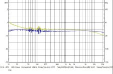
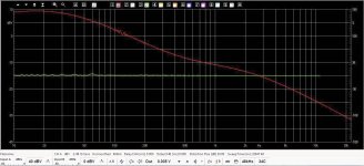
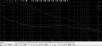
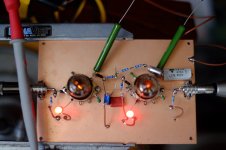
This is what I have so far. Tested with Hagerman inverse RIAA board and without. Built with schematic spec'd parts instead of my hoped for changes just to check the circuit first. C3 is a very old polystyrene - the only one with nominal 1nF value I have around. My meter resolution ends at 1nF so not sure how close it actulally is.How does it work out for your variant?
I don't know yet what the cause of the rough trace 50 - 500Hz is.
The second valve starts to cut-off with more than around 6-7mV input.
Won't the output capacitor being in series with C3 pull that down a touch too?Time constant of the zero: R6C3 = 320 us, where 318 us is required.
Forgive me but I don't now what assumptions you mean.Under the same assumptions, the first pole would be way off: infinite time constant instead of 3.18 ms. I guess the finite gain of the second stage, which I neglected, sets the first pole.
Attachments
I meant my simplifying assumptions that the first valve is a voltage-controlled current source and the second is a nullor, which is about the same as an ideal op-amp. Both are very coarse approximations, as I just wanted to check whether anything is off by a factor of ten.
The assumption about the second valve turns out to be too coarse to even approximately calculate the first pole. That's because the second stage works open-loop at very low audio frequencies. The first pole is therefore not determined by its feedback network, but by the feedback network and the finite open-loop gain of the second stage. This also means that the first pole will be sensitive to variations of the characteristics of the second valve.
It wouldn't if the second valve were a nullor (ideal op-amp). In real life, it will do something on the zero location. I would guess its effect on the zero is quite limited, because its impedance at 2122 Hz is quite small compared to the impedances of the other components, even R8.
The assumption about the second valve turns out to be too coarse to even approximately calculate the first pole. That's because the second stage works open-loop at very low audio frequencies. The first pole is therefore not determined by its feedback network, but by the feedback network and the finite open-loop gain of the second stage. This also means that the first pole will be sensitive to variations of the characteristics of the second valve.
Won't the output capacitor being in series with C3 pull that down a touch too?
It wouldn't if the second valve were a nullor (ideal op-amp). In real life, it will do something on the zero location. I would guess its effect on the zero is quite limited, because its impedance at 2122 Hz is quite small compared to the impedances of the other components, even R8.
- Home
- Source & Line
- Analogue Source
- Passive RIAA Equalization Calculation