
Demian
Ive seen these slides and the goldmund servo thing idea has nowhere the rigidity and simplicity (if you can call it that) of the versa's way of presenting the needle to the phono stage. No headshell/arm tube bending modes issues to speak of. Very elegant design
As for the platter air bearing. I have made platter's that will support 20lbs at less than 1 psi. Its no more than a spin off off the old mapleknoll design with a different spindle design.
Regards
David
The Mapleknoll (I think it is speeled diffurently?) bearing was a one axis air bearing.
The one used by Bicht in the 2.0 was a two axis bearing. vertical lift plus horizontal rotation...
Le Frenchy, the 2.0 used an airbearing with the vacuum hold down, you need a way to pump vacuum into the platter - that has to be up through the air bearing that is pumping pressure. So a hole through the middle of the spindle would seem to be "the way"?
The 1.2, not an airbearing?
_-_-bear
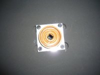
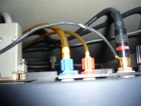
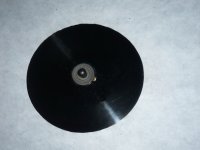
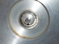
Photos:
The shaft bearing, the arrival of the air tonearm (small pipe), vaccum hold down (large pipe), the axis of the platter and the top of the platter and we see the hole next to the spindle for the vacuum down disc....
The shaft bearing, the arrival of the air tonearm (small pipe), vaccum hold down (large pipe), the axis of the platter and the top of the platter and we see the hole next to the spindle for the vacuum down disc....
Attachments
Demian
Ive seen these slides and the goldmund servo thing idea has nowhere the rigidity and simplicity (if you can call it that) of the versa's way of presenting the needle to the phono stage. No headshell/arm tube bending modes issues to speak of. Very elegant design
As for the platter air bearing. I have made platter's that will support 20lbs at less than 1 psi. Its no more than a spin off off the old mapleknoll design with a different spindle design.
Regards
David
I built a granite based turntable, both the base and the platter were granite surface plates with approx 50 microinch flatness. Very little air was needed to float the platter. The platter weighs around 40 Lbs. The arithmetic is simple, Platter weight divided by square inches of platter is the force to overcome with air. With a really heavy platter the forces of the tonearm/stylus do not show. The challenge was turning down an air pump enough and still having it function. (Not to mention getting a round surface plate. The first sample started out square and the shop just cut off the corners until it was sort of round, kind of fluted really.)
Yes, but this is not an airbearing on the platter.
The 2.0 is a full airbearing on the platter.
What I was commenting on is that in order to have a vacuum hold down on the platter of a full airbearing assembly one would need a hole through the center of the rotating part (spindle) of the unit... and a way to seal it while it rotates... the reference was to the units that 1Audio suggested
I have a 1.2 right now, so I can see exactly the same thing you too pix of...
That bearing seems like a bit of a kludge to me - so far.
_-_-bear
This is a one stop solution for an ultimate turntable: Dover Motion Revolution XL Air Bearing Spindle +Encoder | eBay
It includes an 8 pole brushless DC motor and an optical encoder. Machine a platter and craft a driver/controller for the motor and you are done. Really too simple.
It includes an 8 pole brushless DC motor and an optical encoder. Machine a platter and craft a driver/controller for the motor and you are done. Really too simple.
Any homogeneous stiff material will ring, granite, steel, brass, aluminium etc. The more stiff and uniform the higher the Q. Granite is around 50% Quartz, and really stiff (and stable). One simple trick is to lay two pieces atop each other, the energy is dissipated at the interface. And you would use a mat on the top which will damp it if it were to be excited.
Demian, that is designed to run at speeds up to 25krpm... wonder if will have any torque or control at only 33.333rpm??
I looked at these bearings on ebay and they do seem interesting, the ones with the integral motors look good too...
They are calling for a rather high psi, but is that ONLY required to run them at high speed, will they "float" ok at say half of that, like the Versa 2.0 asked for?? The higher psi is not a show stopper, but it makes it a bit more difficult to implement...
setting up a controller might be daunting without original factory info. I am certainly not well versed in these things... any basic info/tutorial on what the circuitry looks like or the basic requirements (encoder signal conditioning/conversion, the feedback control part, the motor drive requirements, etc...)
Maybe we should take this part to another thread or offline...
Vincent, I have seen the 2.0 bearing, but do not own one.
In essence it is similar to the ones on ebay, sans encoder, motor and with the through hole for the vacuum hold down.
_-_-bear
Are we talking direct drive here? In other words the platter is the "flywheel"??
The data sheet online tells not much.
The Knowledge Center seems to have a glitch in their code so no pages come up, just errors.
Perhaps I will ping them...
The controller is daunting, using the hall effect sensors to commutate the poles... plus the encoder... looks like IF it can work and have enough torque to move a 30-40lb platter or so, you could get out of it for the controller + airbearing motor assembly for ~1,000USD... but one would like one of the surplus units that just HAPPENS to have that vacuum clamp option!!
Dunno... that's a pretty hefty DIY project to spin some garage sale LPs!
_-_-bear
Hall effect motor controllers are not that difficult. I was about to build one for the Rockport at one point. The magic is to use a proportional controller for the commutation. That turns the drive into a very smooth sinusoid for smooth rotation. The speed control comes from the encoder. All of this can be done without digital circuitry even. The platter is enough flywheel. Clearly a DIYaudio type of project. No commercial entity would consider it.
Having a great sense of humor and sarcasm he says: "Hall effect motor controllers are not that difficult". Sure... I can put one together in, ummmm, oh a couple of hours on the bench? Hee hee.
Well, I'd love to build it... would have no problem after reading a number of texts and white papers on WHAT THE HECK THIS STUFF IS!!
Great fun...
_-_-bear
Well, I'd love to build it... would have no problem after reading a number of texts and white papers on WHAT THE HECK THIS STUFF IS!!
Great fun...
_-_-bear
Hall effect motor- hall effect sensors determine the position of the rotor and switch the windings very similar to a DC motor commutator. The speed is controlled by how much DC is available to the switches. its very much a DC motor without a commutator.
More interesting is to use the linear output from the hall sensors (if you can get it) to drive DC coupled amplifiers. This approach has much less torque ripple. The speed is controlled by the gain of the amplifiers, so you need several variable gain amps to make it work.
I'd say 2 afternoons on the bench- after a week of design, sims, layout, parts ordering etc. Not trivial but not beyond the abilities of a committed DIY'er.
That eBay spindle looks like it was designed for a side load rather than a heavy vertical load. I don,t see enough surface area in that direction to support a heavy platter? I,m always thinking low pressure equals low noise but this requires high pressure to function to overcome this kind of load?
Regards
David
Regards
David
- Status
- This old topic is closed. If you want to reopen this topic, contact a moderator using the "Report Post" button.
- Home
- Source & Line
- Analogue Source
- Versa Dynamics TT owners - calling all!