New plots
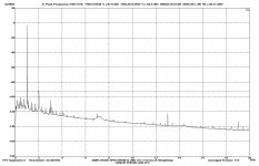
Salas, the problem was the 100pF compensation cap of cartridge in input. I removed it and i did two new FFT plots, one RIAA and one iRIAA. BTW i did and a new FFT analysis, in absolute mode this time with the vertical scale in dBV.
All plots are UNWEIGHTED and smoothing windows are NOT USED.
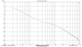
For that -1dB plateau below 400-500Hz something must be done because its a large area octave wise and its possible it will make it a bit weaker subjectively. There lies music's main power range. Can it be needing some easy to change value adjustment in some RC?
Salas, the problem was the 100pF compensation cap of cartridge in input. I removed it and i did two new FFT plots, one RIAA and one iRIAA. BTW i did and a new FFT analysis, in absolute mode this time with the vertical scale in dBV.
All plots are UNWEIGHTED and smoothing windows are NOT USED.
Attachments

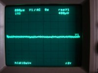
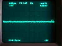
With both inputs of Lineup Phono pre shorted, i tried to capture its real output noise with a Hameg HM502 DSO. It really was a difficult work, because the output fluctuates continuously between 0.4 and 1.2 mV and the lowest scale of DSO is 10mV. For this reason i got two photos, the first indicating the min value and the second the max value. At the same photos, you could see that the output DC offset is really 0 Volts.
Its difficult indeed with just the scope. Can't be capturing long time noise and calculating, its not an analyser. Max value you got shows close to what SNR your FFT showed. Good for cartridges anything 2mV up. For say a 0.25mV typical low MC cartridge it would give 500mV output and 52.4dB SNR. Practical choice for your 2.5mV cartridge to use just a BC560 differential. PR1 and Rg/Rf would dominate anyway. Because HiMC carts are weird creatures, 47K typical input load is not always best for them although almost always found in their manuals, try 1K2 for the Ace Blue if you fancy to evaluate.
dear fotios I am new to the site. I saw your phono amplifier today,and its very interesing.I'll suggest to you to replace all 1N4148 diodes by leds,replacing also emitter"s resistors with the approppriated values. After all these you will notice significant improvement in S/N and also exceptional clarity.
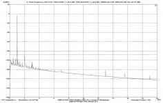
A-Weighted FFT analysis
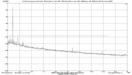
This is a last FFT analysis that i did by using the correct dBFS absolute scale. The measurement is obtained from an ADC converter of a digital interface and its digital noise is always calculated by Virtins MI FFT but is not excluded in scales like dBr, dBV, dBu etc. And as it makes all people, i did the FFT analysis in A-weighting mode.
You can see now, that only the Noise Level is expressed in dBFS (-92.63) while all other parameters remain in percentage and in dB. But this time the digital noise of sound card has been excluded from results. A-weighting offers in reality an improvement of just 3-4dB.
The THD remains at 0.0046% (-86.7dB) and the THD+Noise has been significantly improved at 0.0079% (-82.1dB). The SNR has also improved to 83.9dB.
Attachments
dear folios I am new to the site. I saw your phono amplifier today,and its very interesing.I'll suggest to you to replace all 1N4148 diodes by leds,replacing also emitter"s resistors with the approppriated values. After all these you will notice significant improvement in S/N and also exceptional clarity.
Thanks newcomer for your positive comment and the lecture. In another lecture, i had informed that pink Leds and zorex (it is a new alloy that keeps only NASA) resistors offer the best S/N ratio.

Well, i am just fine with my creation that i made by starting "from the zero". I wish you success in your creations.
This is a last FFT analysis that i did by using the correct dBFS absolute scale. The measurement is obtained from an ADC converter of a digital interface and its digital noise is always calculated by Virtins MI FFT but is not excluded in scales like dBr, dBV, dBu etc. And as it makes all people, i did the FFT analysis in A-weighting mode.
You can see now, that only the Noise Level is expressed in dBFS (-92.63) while all other parameters remain in percentage and in dB. But this time the digital noise of sound card has been excluded from results. A-weighting offers in reality an improvement of just 3-4dB.
The THD remains at 0.0046% (-86.7dB) and the THD+Noise has been significantly improved at 0.0079% (-82.1dB). The SNR has also improved to 83.9dB.
The explanation about dBFS that i did, was rough and is related with the quantization error of ADC converters, included those of sound cards. FS means full scale, i know the term. It is related mainly with the SNR of sound cards, especially in the case (like mine) of using input attenuators. Please, take a look in wikipedia for further information.
BonsaiVery nice looking phono amp Fotios - another great piece of execution. Will you and Lineup publish your complete circuit?
Complete Are already published.
See Part 1
See Part 3
Very nice looking phono amp Fotios - another great piece of execution. Will you and Lineup publish your complete circuit?
Thank you very much Bonsai. I read the first part of your nice article about Phono preamplifiers http://hifisonix.com/wordpress/wp-content/uploads/2010/10/RIAA-Equalization-Amplifiers-Part-One.pdf. It is based on AES papers, it is very explanatory and so a careful reading of it is strongly suggested to EVERYONE HERE. Andrew Russell is a top level Audio designer.
To facilitate you, i will collect all parts of our project in one post.
For Bonsai
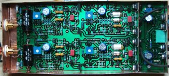
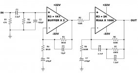
I did a collection of all parts of unit. In the first picture, from left to the right are arranged the cartridge input filter, the input buffer stage, the active RIAA filter and the voltage regulators/stabilizers section.
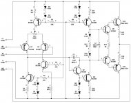
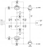
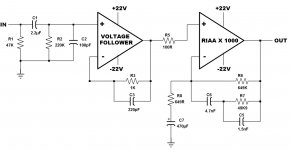
In the second picture is the schematic of the discrete OPA that we use. Four discrete (two per channel) are used. Idle current of output transistors is adjusted at 20mA. The only part that differs in each stage, is resistor R3 that feeds the LTP. In input buffer is 1.1KΩ for optimum THD+N, instead in RIAA filter is increased to 2KΩ for a lower LTP current which offers better handling of output DC offset. We preferred a non inverting RIAA stage, because a series feedback offers a better SNR of 15dB from a shunt feedback. In the third picture is the power supply stabilizer/regulator circuit which feeds with +/-22V the OPAs. In the fourth picture, is the block diagram of each channel with all external parts around OPAs. It should be noted that C2=100pF which is the compensation capacitor of cartridge, during measurements is removed because affects the linearity of plots. Then, is again resoldered in its place.
I did a collection of all parts of unit. In the first picture, from left to the right are arranged the cartridge input filter, the input buffer stage, the active RIAA filter and the voltage regulators/stabilizers section.
In the second picture is the schematic of the discrete OPA that we use. Four discrete (two per channel) are used. Idle current of output transistors is adjusted at 20mA. The only part that differs in each stage, is resistor R3 that feeds the LTP. In input buffer is 1.1KΩ for optimum THD+N, instead in RIAA filter is increased to 2KΩ for a lower LTP current which offers better handling of output DC offset. We preferred a non inverting RIAA stage, because a series feedback offers a better SNR of 15dB from a shunt feedback. In the third picture is the power supply stabilizer/regulator circuit which feeds with +/-22V the OPAs. In the fourth picture, is the block diagram of each channel with all external parts around OPAs. It should be noted that C2=100pF which is the compensation capacitor of cartridge, during measurements is removed because affects the linearity of plots. Then, is again resoldered in its place.
Attachments
Last edited:
Measurement setup
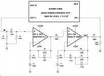
Here is a picture indicating the measurement setup. The problem is this: The ADC converter of sound card can accept up to 1.5Vp in its input without risk. The phono preamplifier has a gain of 2 in first stage, and a gain of 1000 in RIAA stage, total 2000. A signal of 2.5mV produced from the function generator of Virtins MI software FFT analyzer, will be multiplied by 2000 from the preamp, so in its output will be 5Vrms or 7Vp. For this reason, i use a 10:1 voltage divider (R9/R10) in the output of preamp to reduce the signal in a safe value for the ADC input of sound card. Because the sound card is not a Audio Precision analyzer the voltage divider is a trick which protects sound card but affects the I/O calibration ratio of FFT software. For this reason i used in the first FFT analysis dBr (relative) units, no smoothing window and unweighted analysis.
Now i use absolute units (dBV) in the plots of THD and Noise FFT analysis.
Attachments
Measurements
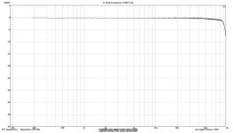
There are frequency response and THD+Noise measurements obtained from the Virtins MI Pro 3.2 software and the ASUS Xonar Essence STX sound card. In all FFT plots window function is NOT used.
The first plot is the RIAA response of preamplifier. The second plot is the response in inverse RIAA for which i used the Hagerman iRIAA circuit in preamp input. In both plots the vertical scale is expressed in relative mode (dBr).
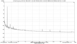
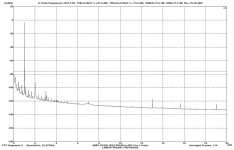
The third plot is an UNWEIGHTED FFT analysis of THD and Noise, while the fourth plot is the same but this time A-Weighted. In these plots, i used a vertical scale in absolute mode (dBV). I think that a SNR of 73.2dB unweighted and 84.5dB A-weighted is just fine. In all measurements, the THD is less than 0.005% and the THD+Noise is less than 0.05%. These limits was our target from the begining and not the noise because we knew it that by anyway will be very small.
The last two pictures are the net output noise captured with a DSO. The first shows the low limit and the second the high. A mid value it is very close to the 73.2dB measured from the Virtins FFT analyzer. Thanks to the trim-pots used in each stage of preamp, the DC offset is 0V so it can be direct coupled in the next stage. There is no need for AC coupling capacitor.
There are frequency response and THD+Noise measurements obtained from the Virtins MI Pro 3.2 software and the ASUS Xonar Essence STX sound card. In all FFT plots window function is NOT used.
The first plot is the RIAA response of preamplifier. The second plot is the response in inverse RIAA for which i used the Hagerman iRIAA circuit in preamp input. In both plots the vertical scale is expressed in relative mode (dBr).
The third plot is an UNWEIGHTED FFT analysis of THD and Noise, while the fourth plot is the same but this time A-Weighted. In these plots, i used a vertical scale in absolute mode (dBV). I think that a SNR of 73.2dB unweighted and 84.5dB A-weighted is just fine. In all measurements, the THD is less than 0.005% and the THD+Noise is less than 0.05%. These limits was our target from the begining and not the noise because we knew it that by anyway will be very small.
The last two pictures are the net output noise captured with a DSO. The first shows the low limit and the second the high. A mid value it is very close to the 73.2dB measured from the Virtins FFT analyzer. Thanks to the trim-pots used in each stage of preamp, the DC offset is 0V so it can be direct coupled in the next stage. There is no need for AC coupling capacitor.
Attachments

Thank you very much Bonsai. I read the first part of your nice article about Phono preamplifiers http://hifisonix.com/wordpress/wp-content/uploads/2010/10/RIAA-Equalization-Amplifiers-Part-One.pdf. It is based on AES papers, it is very explanatory and so a careful reading of it is strongly suggested to EVERYONE HERE. Andrew Russell is a top level Audio designer.
To facilitate you, i will collect all parts of our project in one post.
Thanks Fotios.
Lol - I don't know about being a top audio designer, but I am having a lot of fun!
Last edited:
Variation of Lineup Phono Stage
Because my cartridge (Benz Micro ACE-H M.C.) has an output of 2.5mV, i followed the recommendation of Salas. The initial circuit, presents a total gain of 66dB (max output = 5Vrms) which is big. To reduce the gain, i did a modification in the first stage. I changed it from non-inverting buffer with Av = 2, to a simple Voltage Follower with Av = 1. So, the max output has reduced at 2.5Vrms (Av = 60dB). The discrete OPA that we use, has an amazing performance as Voltage Follower! I will show this in other post. The result was an improvement of THD+Noise and Noise Level of the whole circuit. The response in RIAA or inverse RIAA is the same like in the initial circuit.
Here is the block diagram and an A-Weighting FFT analysis (NO smoothing window).
Attachments
Hi
nice looking phonostage but I have one question...
won't your second x1000 stage just be amplifying the first gain stages output noise as well? Surely it would be better to x1000 first off from your cartridge as the noise output from your cartridge is lower than the thermal and electrical noise associated with the x2 buffer?
I'm just a novice but it looks wrong to me...what am I missing here?
Rob
Hi Fotis
The BC560 is OK for 2.5mV cartridge but the 2N4401 has better noise spec and paralleled 2N4401s are even better. But I would x1000 first then off to the x1 buffer. I have tried paralleling 2N4401 and needed to parallel at least 8 to be able to use a decent 0.25mV cartridge.
Is your modified 918 the new opamp you have developed which is on your website? I am trying to implement some of your ideas on the JE990 opamp.
Rob
When stages are cascaded, the input one's noise totally dominates over the second's when there is about equal or more gain allocation to it than in the 2nd. When the first stage has no gain, the second stage must be designed for low noise too is the requirement. In this one both are the same quality, the cartridge is high output and the unweighted results look fine, so no worries IMHO. In principle, the head amp gets to be the lowest noise design and should have ~30dB gain to write off the second's noise non the less. If it was for low MC, the going gets tough and the low Rbb' of devices like 2N4403 comes to play indeed. The PNP arrangement that is used here, usually has closer hfe samples in same batch than NPN, useful for the LTP, and lower base resistance than the NPN counterpart. Indifferent in the presence of PR1 in the particular design though.
- Status
- This old topic is closed. If you want to reopen this topic, contact a moderator using the "Report Post" button.
- Home
- Source & Line
- Analogue Source
- Phono preamplifier from Lineup & Fotios