I did a lot of research into the different types of bearings and did look at olives/ring bearings. My conclusions were that Vees still offer lower friction but at the cost of lower maximum load. The vees are self loading so there is no chance of chatter whereas the ring or olive bearings could vibrate against the end stops when used with a horizontal axis, there has to be a little bit of play. Vees are self aligning, as are olives to a lesser extent. Rings need very precise alignment. And maybe most importantly vees offer the best mechanical grounding.Quote, Niffy, they are the best for sure - but with a 90° load why not a ring jewel instead of vees?
c
Hi niffy, does your pivot and jewels have the same radius?
I thought the idea was to have a smaller radius on the pivot so that there is a point contact.
The pivots have a radius of about 0.125mm, the vees have a radius of about 0.25mm. That's actually quite large for this type of bearing. I went for the large size as I was a bit paranoid about bearing wear, I could probably have gone for a smaller radius.
Niffy
Thanks Niffy, surely those who build linear tonearms must have a refined culture for bearings, especially for friction issues. I had bad experiences (low hz discharges) with ball bearings at the beginning, so now my ears are sensitive (or imagine to be) to the chattering, and I try to avoid them as possible.
Like you, with the experience I got the idea that the arms must be "mechanically grounded", that resonances must be absorbed far from the cartrige, never letting them to be reflected backwards: no decoupling, no damping for a clean sound, imho.
Many who know much more than me think the opposite, and build beautiful sounding arms.
For me the problem of jewells is the availability, the industrial cost now does not seem too different from pen nibs.
carlo
Clever, Doug, as usual. Sometimes my Rabbit too feels a little down mood...
Is it there a spring inside? do not understand the role of the metal side rod
carlo
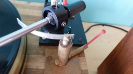
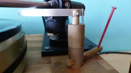
forgot to post this: works fine, easy diying: but pay attention to the fabric hinges (very thin) and glue (white, well diluted)
Is it there a spring inside? do not understand the role of the metal side rod
carlo
forgot to post this: works fine, easy diying: but pay attention to the fabric hinges (very thin) and glue (white, well diluted)
Attachments
Carlo,
That could be built on a kitchen table with an Exacto knife and a little care. And bearing chatter certainly can't be a problem.
The lifter does have a spring. If it were built of metal, which wouldn't be hard, and lubricated with heavy silicone, it would probably self-lower slowly.
The metal rod is there to prevent a small amount of twist as the piston raises and lowers. Better construction might eliminate the need.
Attachments
Meanwhile ....
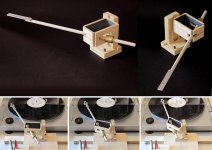
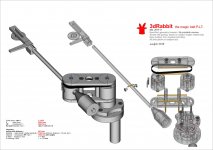
the 3dRabbit's print-files have been -slowly- completed: improved geometry, better than in my metallic version, reinforced structures (in 3D printing hollow shapes may be sturdier than solid ones with infill), easy settable bearings.
But: now I have no will and time to print and test it. So if someone does it, will have the good or bad surprise of knowing directly if it works, or not. In that case don't send me to hell, i did what i could.
Good luck to every brave diyer, since real PLTs are far different from virtual ones
carlo
Attachments
Last edited:
That arm looks great Carlo. What did you design this to use as the vee part of the bearings where the pen tips sit?
On your 3DToy arm, I believe you designed it for brass set screws that had a vee made by a center drill.
The Bunny looks like it uses something different.
On your 3DToy arm, I believe you designed it for brass set screws that had a vee made by a center drill.
The Bunny looks like it uses something different.
Yes - same pentips bearings as in 3d toy, with just a little mod to avoid the fact that in PLA the threads do not last long: 3mm rivets epoxied to plastic, threaded 2.5mm inside for the v screws
Sorry not to test it. but my old Rabbit works so well...
carlo
ps the Rabbit has just 1 bearing more than a traditional gimballed TA: and -imho- this is crucial to make a working non-servo PLT
Sorry not to test it. but my old Rabbit works so well...
carlo
ps the Rabbit has just 1 bearing more than a traditional gimballed TA: and -imho- this is crucial to make a working non-servo PLT
That arm looks great Carlo. What did you design this to use as the vee part of the bearings where the pen tips sit?
On your 3DToy arm, I believe you designed it for brass set screws that had a vee made by a center drill.
The Bunny looks like it uses something different.
Just making a depression in the end of a grub screw with a drill bit will not make a very good vee. It will have a flat bottom, straight angled conical sides at a shallow angle and a rough surface. Proper vees do have conical walls but at a steeper angle, normally 45°, so the tip is at 90° . The bottom of the vee is also spherical, mine had a radius of about 0.25mm for use with pivots with a tip radius of about half this.
When I made the experimental vees for my linear arm I used M3 stainless steel grub screws. To make a correctly profiled vee I made a punch from the shaft of a 6mm drill bit. I cut the drill and ground the end at 45° to give the correct 90°. I polished this to give a smooth surface. With this mounted in my pillar drill, using a fine file, fine wet and dry paper and under high magnification I rounded the tip. I used a 0.5mm drill bit shaft as a reference to make sure I got the correct radius. I again polished this.
I flattened the ends of the grub screws and using a centre drill put a small impression in the centre to align the punch. I tapped an M3 hole in a piece of scrap steel and set the flat end of the grub screw flush with the surface. This is a very important step as I prevents the thread being distorted when being punched. I aligned the punch in the end of the screw and tapped it with a hammer. I now had a near perfectly shaped vee. I polished the vee using a pointed matchstick and polishing compound and my dremel.
The pivots were made in a similar way to making the punch. I used hardened steel sewing pins.
If using fine tip ballpoint pen nibs the radius of the vee will need to be quite large, about double the radius of the nib. Larger radius pivots and vees will yield higher friction, more play and poorer mechanical grounding.
Although the coefficient of friction between brass and steel is lower than between steel and steel utilising steel grub screws for the vees will actually yield lower friction as steel is much harder than brass. With this type of bearing it is the hardness of the materials used that has the greatest influence on the resultant friction. Another possible benefit of using the punch method (cold forging) is that the act of punching should work harden the surface layer of the metal in the vee. I have no idea how significant this will be for bearing performance but it can't hurt. I found that the application of a small amount of petroleum jelly into the vees seemed to make the bearing run a bit more smoothly though I did not measure how much effect this had on overall friction levels (I did measure just about everything else).
The amount of work required to make bearings using this method is much greater than just drilling a pit in the end of the grub screw but it does result in a much higher quality end product.
Niffy
Valuable and interesting advices and experiences, Niffy. I gave some simpler tips on # 1859
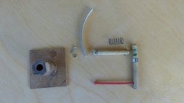
--To make the brass cup grains (the trickiest work of this arm) drill and thread an iron block to guide a center drill and make the conical seat, then polished with a small Dremel tip.
More than enough for a 3dToy, for two reasons
1 - a center drill is not a normal drill bit but a precision tool used on lathes - mills to center holes precisely: it does not make a flat surface, but a starting 118° cone, quite smooth if of decent quality/age. A further polishing with a Dremel may help,
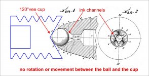
2 - with a ball pen tip there are not two surfaces (steel + steel or steel + brass) crawling against each other, but a sphere that rotates in its seat (the pen tip) The vee cup simply holds the sphere in the right position (related to arm's geometry). At the beginning, following the experts, I emptied all the ink with solvent, then I discovered that ink is a much better lubricant, for viscosity and durabilty, of what I used to put in (silicon grease)
that's all folks - let's not complicate our life where it's not needed
carlo
--To make the brass cup grains (the trickiest work of this arm) drill and thread an iron block to guide a center drill and make the conical seat, then polished with a small Dremel tip.
More than enough for a 3dToy, for two reasons
1 - a center drill is not a normal drill bit but a precision tool used on lathes - mills to center holes precisely: it does not make a flat surface, but a starting 118° cone, quite smooth if of decent quality/age. A further polishing with a Dremel may help,
2 - with a ball pen tip there are not two surfaces (steel + steel or steel + brass) crawling against each other, but a sphere that rotates in its seat (the pen tip) The vee cup simply holds the sphere in the right position (related to arm's geometry). At the beginning, following the experts, I emptied all the ink with solvent, then I discovered that ink is a much better lubricant, for viscosity and durabilty, of what I used to put in (silicon grease)
that's all folks - let's not complicate our life where it's not needed
carlo
To be clearer.
A ballpen tip is a masterpiece of micromechanics, that no diyer and even a Swiss watchmaker could reproduce (the Chinese themselves who make 95% of the ballpens sold, only in 2017 have managed to make the machines to produce them, instead of buying and assembling them! - Consider that presently they design and build SmartPhones, not bamboo baskets).
In our use (Unipivots & so on) the pen tip must do all the work: the sphere does not rotate on the vee cup. but in its seat, on an ink or grease film). That's why the vee must be 120 degrees or more (not 90!), otherwise is the brass body to rub against the vee cup (and then much better the steel pivot that Niffy talks about)
hope this helps, even if we are off topic
carlo
Attachments
Last edited:
1. It's not a pivoting arm.
2. Vertical motion of the headshell causes an azimuth shift. There is already an inherent azimuth shift in the surface angle of a record warp and the behavior of this arm compounds that.
I am neither amused nor interested.
Ray K
Quote all, Ray, completely: a waving, rolling azimuth is a real nightmare. Adding a second carriage, when just one is more than a problem seems masochistic.
However a cartridge simply sliding on a radial rail represents the perfect geometry: you've only to design a perfect "piston-like" vertical articulation, and to overcome all the issues of the Revox linear tracker. Without a servo, of course.
Nice challenge, nobody till now...
carlo
My compliments for you new arm, Ralf: a superb realization
- Home
- Source & Line
- Analogue Source
- Angling for 90° - tangential pivot tonearms