How did you calculate the curves from desired arm length?
You are right, the pivot point can be any point between the wheels, I just went geometric center for esthetics.
If you want I can calculate the curves for you, I would need arm length and the (x, y) translation of the curve starts from pivot point for all 3 wheels.
Or for one curve and then derive the other 2 from mechanical simulation like it seems you've done here. Nice idea if you did this.
The results will come as an array(x, y, z) in text. You can then use that data to plot your curve(s).
Sent from my ALE-L21 using Tapatalk
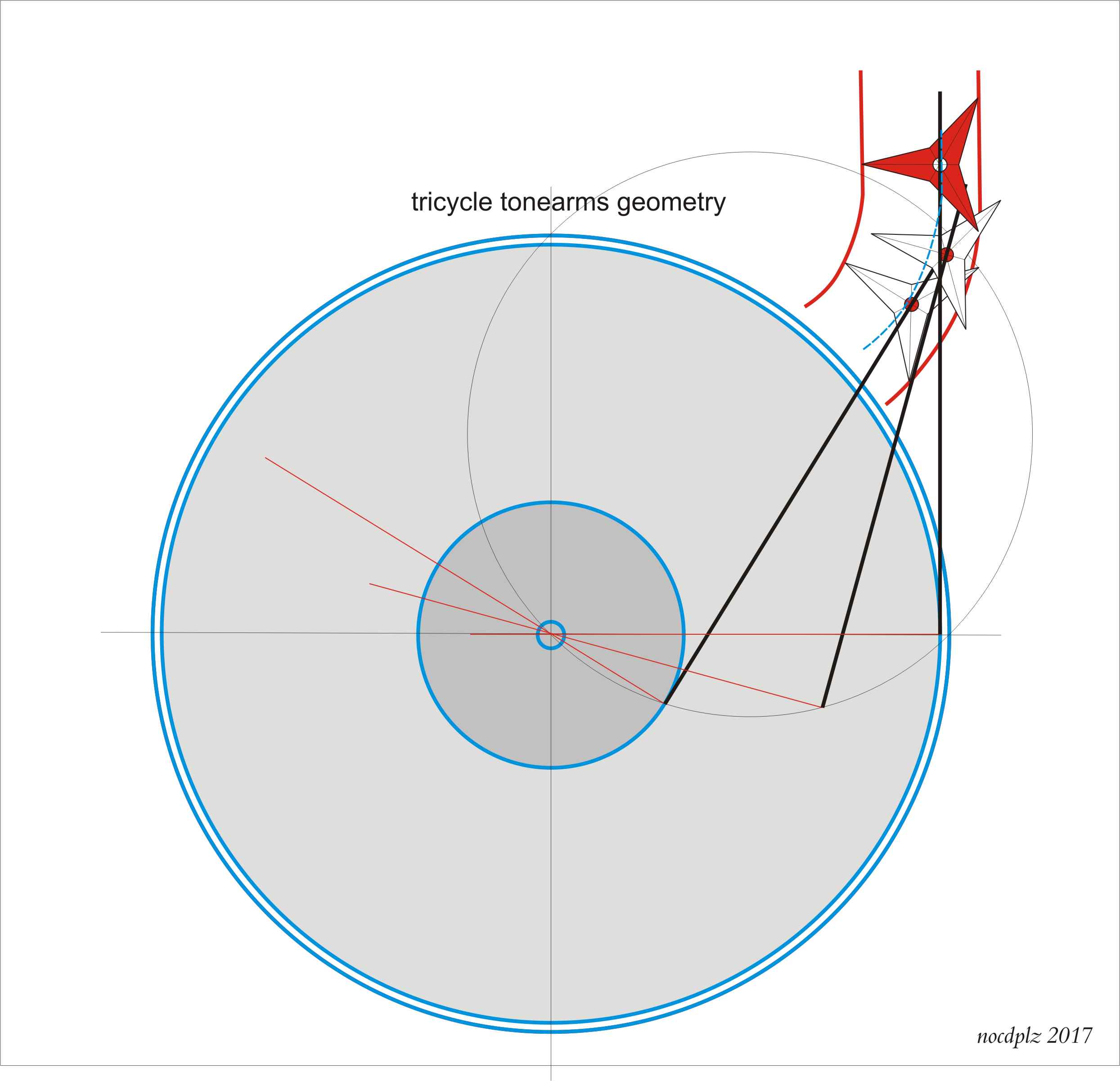
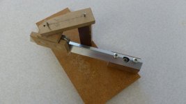
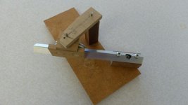
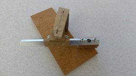
I can not calculate them, so I've got it graphically (my graphical program allows to rotate complex objects at any chosen point).
Doing so i've found that the center of bisectors does not work, while the center of the circumscribed rectangle is ok. Do'nt ask me why: the wheels bring a different basis in every point of the curve: really complex.
This mockup is made with a gradually "shrinking" curve, to test if and how this tricycle was able to follow. Not the Dd tricycle curve
As said I got the curves mechanically, marking dots in many different positions. For a working arm maybe a cnc mill and a good cad is needed (few thous. of tolerance). But after making the "inner guide solution" I think it can be done by hand, with progressive adjustments: also today precision lathes or mills are brought to the top with manual scraping.
Carlo
have you noticed the sliding pivot of the third wheel?
pivot point on tricycle
Dear 2wice, that's what i'd found in my graphs. (attachment) And it's drawn considering just triangles, not wheels! Since you did the math of that curves can you explain to me? It was shocking for me.
I've read (#1133) that you made a mechanical model on 3 jewel bearings on a rigid triangle, tracing 3 guides: can you show us the results? have you got problems?
ciao carlo
Attachments
It was a digital model. Vertical wheels did not work in simulation so 90deg wheels was the idea, same as yours.
You can find the approximate maths plot in #964 and some more info in #1119.
I have a spreadsheet that spits out the curves according to parameters. Most of the plots disappeared when dropbox nerfed hot linking.
Sent from my ALE-L21 using Tapatalk
You can find the approximate maths plot in #964 and some more info in #1119.
I have a spreadsheet that spits out the curves according to parameters. Most of the plots disappeared when dropbox nerfed hot linking.
Sent from my ALE-L21 using Tapatalk
(attachment) And it's drawn considering just triangles, not wheels!
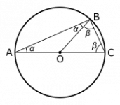
Since you use the Thales semi-circle, I'm surprised that the three black lines do not converge to a single point at the edge of the circle. The inner two lines seem to be right but the outer line crisscrosses with the other two. I'm baffled.

In your next drawings, can you add a straight line from the spindle to the converged point for easier illustration?
I favor this, too. I imagine a purely mechanical construction being too sensitive to sound and other vibration -- the Thales construction even needs an anti-skating unit. So we rather had a bone a bit longer than disc radius, bone bearing mounted and moving on a track perpendicular to the bone. This movement were controlled by a regulator, which strives to keep bone-to-track-angle perpendicular. If you moved the head to a certain location on the disc, the base would follow suit. Only problem is to build a track-with-base, which is not too sensitive to dirt, so movement stays smooth and well.IMHO, all mechanical nightmares that probably introduce as many problems as they cure. Here's what I've been thinking about, but have yet to build. Pivoted tone arms are highly developed and work well, but I think that offset introduces forces that cause more trouble than can be fixed with anti-skate mechanisms, not to mention the obvious problem of getting the angle right at only two points. Rotating the head of an offset arm is not the answer! You must eliminate the offset. So, keep the standard tonearm, remove the offset and make it a bit longer. Now, just drive the pivot assembly along the back of the turntable in a track. Servo it, probably photoelectrically, but don't try for perfection. Let the tonearm do what it was designed to do. Try for silence and smoothness on the drive. I'm not sure what the best drive method would be, maybe a lead screw and DC motor, maybe a thin thread and drum drive or even a linear motor track. This is basically an electronic forum, so moving the pivot under motor control shouldn't be too difficult. The angular error will be very small even if the pivot location is off a couple mm- no human can align a cartridge that close regardless of what they claim. Maybe line the track with Teflon tape and/or make it a V-way for better stability. IMHO again, any system that tries for a rigid coupling between the tone arm and track (like air bearing arms) creates a horizontal mass problem that's completely unnecessary. The arm in this design can be a unipivot or whatever you like.
I'm not worthy...
... okay I am, but...
hi guys,
just a quick note. I've been following this thread for some time (and have made a few comments along the way). There seems to be a huge range of ideas presented here. I am not against any, however, but must ask the question (simply), why?
To me the simplest solution seems to be the easiest to imagine, but the most difficult to implement (in terms of DIY) due to the required precision of the component construction.
Somewhere in this thread, Schröder (IIRC) suggested 2 ideas that should be worthy of further consideration. Namely the use of an arm between the headshell and the spindle. If sufficiently good bearings can be used this seems quite reasonable. The other is the use of a secondary "vertical" arm with it's own counterweight attached to the headshell. The only thing that is of issue here is the accuracy of the headshell, the correct weight, and aligning the weight correctly.
I think that a modern Gerrard 'zero" arm implementation would be something to look at closer as well.
The other idea that has a lot of merit is the use of a very precise and low friction miniature electric motor type bearing and just let the cartridge track its natural path in the groove.
Of course there is real merit in the use of a physical arc guide for a moveable bass and of an optically sensed/controlled motor system to drive a string (or screw shaft). Again, the precision required may elude many.
IMHO, all mechanical nightmares that probably introduce as many problems as they cure. Here's what I've been thinking about, but have yet to build. Pivoted tone arms are highly developed and work well, but I think that offset introduces forces that cause more trouble than can be fixed with anti-skate mechanisms, not to mention the obvious problem of getting the angle right at only two points. Rotating the head of an offset arm is not the answer! You must eliminate the offset. So, keep the standard tonearm, remove the offset and make it a bit longer. Now, just drive the pivot assembly along the back of the turntable in a track. Servo it, probably photoelectrically, but don't try for perfection. Let the tonearm do what it was designed to do. Try for silence and smoothness on the drive. I'm not sure what the best drive method would be, maybe a lead screw and DC motor, maybe a thin thread and drum drive or even a linear motor track. This is basically an electronic forum, so moving the pivot under motor control shouldn't be too difficult. The angular error will be very small even if the pivot location is off a couple mm- no human can align a cartridge that close regardless of what they claim. Maybe line the track with Teflon tape and/or make it a V-way for better stability. IMHO again, any system that tries for a rigid coupling between the tone arm and track (like air bearing arms) creates a horizontal mass problem that's completely unnecessary. The arm in this design can be a unipivot or whatever you like.
Conrad
I favor this, too. I imagine a purely mechanical construction being too sensitive to sound and other vibration -- the Thales construction even needs an anti-skating unit. So we rather had a bone a bit longer than disc radius, bone bearing mounted and moving on a track perpendicular to the bone. This movement were controlled by a regulator, which strives to keep bone-to-track-angle perpendicular. If you moved the head to a certain location on the disc, the base would follow suit. Only problem is to build a track-with-base, which is not too sensitive to dirt, so movement stays smooth and well.
While I agree on the merits of a servo driven pivoted arm to achieve linear tracking (I have diy'd my own), the OP stated that he wants to achieve tangential tracking without the use of electronic servos or air pumps, and I feel we should respect that by not turning this thread into a linear versus pivoted debate. I too, think that skating is evil, but there are some articulated designs that exhibit zero skating in the middle area of the disc and little skating at the inner and outer grooves, much less overall than a 9 inch conventional offset pivot arm. Quite frankly, I've been amazed at the ingenuity I've seen on this thread.
Ray K
... okay I am, but...
hi guys,
just a quick note. I've been following this thread for some time (and have made a few comments along the way). There seems to be a huge range of ideas presented here. I am not against any, however, but must ask the question (simply), why?
Why?
Because we want to. [emoji14]
Not sure what motivates others but mine is discovery, learning, seeing something done differently, not necessarily because it is better but because it is new and different. If by the off-chance it is better, what a bonus that would be. [emoji4]
Sent from my ALE-L21 using Tapatalk
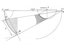
Back to the skate thing, again. I believe there is NO SKATE inherent in the Birch design. Looking at the Thales Theorum, the line A - B is equivalent to the Birch tonearm with the pivot at point A and the stylus at point B. The stylus is aligned to that line at all points. There is no other way to build it, so no offset, no skate.
Birch point B is the main pivot and the two guide arm pivots, in conjunction with the B pivot, make the controlled effective length extension possible. If the Birch guide arm at point P in the Birch is removed, the remaining arm pivoting around point B can still work, although not well. If point B in the Birch drawing is removed, there is nothing that can be called a tonearm, but something like stiff spaghetti.
As Frank Schroeder has pointed out, there are SIDE FORCES. They result from bearing friction, effective horizontal mass, and the guide arm can overshoot - or undershoot on an eccentric LP. The last factor is where diyrayk's string test comes in to play.
Attachments
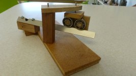
DD, Is the model in the photos something close to your split plane idea? The geometry will work, but the construction comes with all the usual caveats about bearings, precision, etc. I haven't included the front arm, vertical bearings, or headshell.
If I made a serious attempt at building this one, I'd sling the bearings under the track so it would be supported at two points including right under the vertical bearing housing and close to the CW. I'd probably steal some ideas for the bearings and track from our passive linear tracker friends.
If I made a serious attempt at building this one, I'd sling the bearings under the track so it would be supported at two points including right under the vertical bearing housing and close to the CW. I'd probably steal some ideas for the bearings and track from our passive linear tracker friends.
Attachments
Why?
Well of course that's the answer, Captain Obvious...
Different for it's own sake is irrelevant (IMHO). Different seeking improved sonics is noble. Real difference may require a higher degree of machining precision than almost all here are challenged by. Is DIY dependent on who has a better set of tools (and hence more $$$'s invested in said tools)? Or the cash to have something machined for them?
If something cannot be built on a kitchen table (or in typical home workroom or workshop using typical home tools) then it all comes down to who has the biggest budget to spend on these experiments.
Why?
Because we want to. [emoji14]
Well of course that's the answer, Captain Obvious...
Not sure what motivates others but mine is discovery, learning, seeing something done differently, not necessarily because it is better but because it is new and different. If by the off-chance it is better, what a bonus that would be. [emoji4]
Different for it's own sake is irrelevant (IMHO). Different seeking improved sonics is noble. Real difference may require a higher degree of machining precision than almost all here are challenged by. Is DIY dependent on who has a better set of tools (and hence more $$$'s invested in said tools)? Or the cash to have something machined for them?
If something cannot be built on a kitchen table (or in typical home workroom or workshop using typical home tools) then it all comes down to who has the biggest budget to spend on these experiments.
DD, Is the model in the photos something close to your split plane idea? The geometry will work, but the construction comes with all the usual caveats about bearings, precision, etc. I haven't included the front arm, vertical bearings, or headshell.
If I made a serious attempt at building this one, I'd sling the bearings under the track so it would be supported at two points including right under the vertical bearing housing and close to the CW. I'd probably steal some ideas for the bearings and track from our passive linear tracker friends.
I think you got the idea. It's not how I visualized it but the concept is similar. I thought of using two rollers on axle acting as carriage AND vertical bearings. Below is something I rough sketched up a year ago using a string as the guide since the stylus is always moving forward. But my friend told me when encountering eccentricity the string might slack and create problem so maybe something with rigid like a thin carbon fiber rod as guide. It's probably better to have the main arm under the track like your suggestion. Again, this picture is from a year ago and I might do it differently now. But since it's the only sketch I have so I posted here. I wish I have the graphic skill like Carlo's! And yes, taking idea from other genres of arm is beneficial to any DIYers.

Dear Direct driver, beautiful paintings are hanging in museums: we need just drawings that clearly represent a project. Your is so good that now i can see what I could not understand from words. This is the essential: a clear drawing is also nice, a nice one that can not be understood not only is ugly, it's stupid!
It seems that the tricycles were abandoned (after my tests, I understand why!) for an extensible Thales? The separation of the planes is indispensable for not having VTF variations, isnt it? great!
I'm still in doubt to entrust the movement only to the stylus drag, a very weak and very variable force. I'm afraid that if we can reduce all the frictions of the pivots, the stylus will overcome the tangency point until bending prevents it from going further: so we will have again the tracking error and the skating we wanted to avoid.
Working on mine, after a first mock up of B solution (incredible, it elongates with just 3 grams! so, how weak must be the spring in a well built tonearm?) I came to this C, with two strings.
carlo
post #1266 I was applying 2wice curves to my tricycle, not the Thales! ops, the lack of tangency is a stupid mistake
Doug: clever solution, and clever mockup!
Attachments
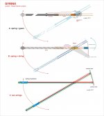
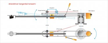
Correctly interpreting your drawing, Dd?
flanged bearings may avoid strings?
Brilliant! Thanks Carlo for visualizing my thoughts. Your graphic skill is such an asset to this thread!
Some thoughts on the arm:
From an ergonomic standpoint, the main arm should be at least 6" long so the counterweight is not touching the platter, unless you have extra wide platter a la EMT 927. You can of course make it extra short like the Trans-Fi arm or other airbearing short arms and make the counterweight not low hung. I originally wanted the main arm long enough so the vertical bearing is on the same plane as the platter to have consistent VTF. But a shorter arm has its benefits too. It's a designer and user decision.
Having the horizontal carriage above the main arm makes any guiding system easier so the main arm is not in the way of strings or rods or magnet or whatever. This is really taking the Dynavector 'split-plane' idea and give it a twist. The horizontal bearings have a hole that wires can thread through or make a plug so user can swap out arms. I want the main arm and rollers able to be detached from the horizontal rails so it's easier to mount cartridges. Or you can make multiple arms+rollers pre-mounted with different cartridges for flavors.
The roller design can be other bearings like pin wheel bearings or even make the main arm vertical movement completely independent from the carriage. I just like the simplicity of forward movement AND vertical movement accomplished using only two ball bearings.
The arm-lift is tricky though. Because your pictures have it installed on the horizontal bar that it has horizontal movement during play and if you're not careful you can swipe out and destroy the cartridge! It has to be a two hand operation: lift cartridge up with finger lift and then apply lever to hold arm in tilt position. There should be a more elegant solution. Thinking....
The guiding mechanism needs elaboration. If we use a single string, the tie point has to be at the mid point of the axle to comply with the Birch geometry. We can drill a tiny hole through the axle midpoint for the string to pass through with a tied knot at the axle end going to the other tied point. As I said, eccentric record can possibly create slack in the string and lose tension intermittently and that can cause problems. I think your two string approach can be adopted into this design just as Doug's approach can be also adopted. I think the fun part of this kind of design is to come up with creative ways to 'cheat' the geometry.
Conceptually, it's pretty simple: we must make the arm move forward and/or extend longer as it tracks closer to the spindle and the Thales semi-circle is our guide. Another approach using only pivot bearings instead of linear bearing is to use a parallelogram for the top horizontal part. You will end up with at least six pivot points instead of two rollers. It might look too Rube Goldberg though.
Thanks again, Carlo, for making it easier to explain my thoughts. I would like to see this on your kitchen table one day!
The arm-lift is tricky though. Because your pictures have it installed on the horizontal bar that it has horizontal movement during play and if you're not careful you can swipe out and destroy the cartridge! It has to be a two hand operation: lift cartridge up with finger lift and then apply lever to hold arm in tilt position. There should be a more elegant solution. Thinking....
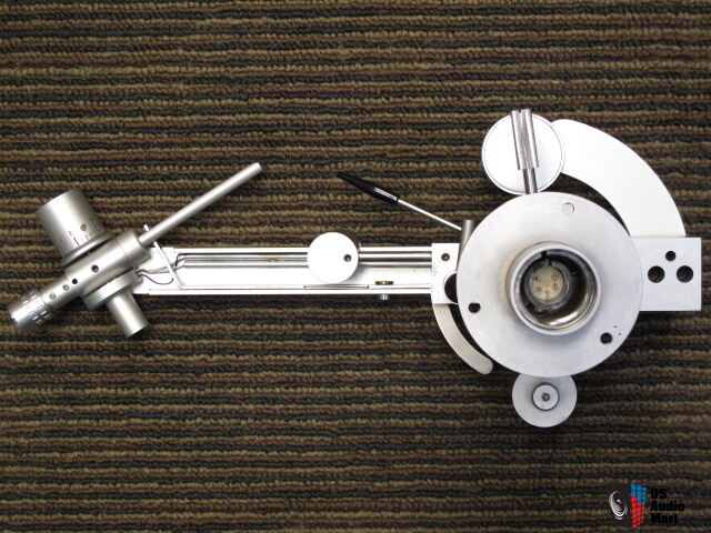
Since we are fans of the Dynavector split-plane approach, why not utilize their arm-lift solution?
As far as I remember, it uses a small lever under the "horizontal movement arm" which engages another small lever directly below the "vertical movement arm".
Here is a photo of the underside of a Dynavector arm to perhaps further clarify:
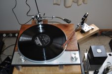
I don't know if anyone posted this diy arm. Here is the link.
http://www.lencoheaven.net/forum/index.php?topic=9746.0
http://www.lencoheaven.net/forum/index.php?topic=9746.0
Attachments
- Home
- Source & Line
- Analogue Source
- Angling for 90° - tangential pivot tonearms