It would be enlightening to have Vidmantas Triukas of Reed and Helmut Thiele of Thiele join us here. There are unique elements to both designs and I think a lot of thought has gone into their PLTs. If they would be willing to talk about some of their objectives and decisions, there could be some very interesting discussions.
Frank,
I have a question for you. However, if you don't want to answer because there may be some trade secrets involved, I understand it completely.
The magnet guide rail seems like 5 mm or less in width for your LT tonearm and the magnet above the rail is about 5 mm or less in diameter, too. Is the magnet strong enough to accurately control the angle of the arm? If there is eccentricity, the arm will be forced to move back a little. Is the force of the magnet rail strong enough to hold the magnet in the middle of the rail? Or is it possible that the magnet holds the arm in the same position so the stylus will not be tangent to the groove? Your CB tonearm has a magnet bearing as well. I understand the magnet is strong and performs a simple task. But not in the case of the LT arm, the magnet needs to perform accurate and complicated tasks.
Jim
Last edited:
Hi Jim,
You have it wrong, - the non-contact guide slot is only there to keep the user from pulling the magnet too far away from the 2mm "rail"(soft iron rod) which sits embedded in the bottom of said slot. The attracting force between the magnet and the rail is always strong enough to pull it back to minimum proximity(how else would it be able to function") ?
?
All the "Birch" arms currently under discussion will move back and forth if an eccentric record is to be traced.
In the CB tonearm, the magnetic circuit is just strong enough to perform its task: Centering/pre-loading the single ceramic hybrid bearing, so there won't be any change for chatter or location indifference.
LT or not, a magnet cannot perform its task in a more or less accurate way, it's just looking for the closest mate and in that, the lowest potential"
Cheers,
Frank
You have it wrong, - the non-contact guide slot is only there to keep the user from pulling the magnet too far away from the 2mm "rail"(soft iron rod) which sits embedded in the bottom of said slot. The attracting force between the magnet and the rail is always strong enough to pull it back to minimum proximity(how else would it be able to function
?All the "Birch" arms currently under discussion will move back and forth if an eccentric record is to be traced.
In the CB tonearm, the magnetic circuit is just strong enough to perform its task: Centering/pre-loading the single ceramic hybrid bearing, so there won't be any change for chatter or location indifference.
LT or not, a magnet cannot perform its task in a more or less accurate way, it's just looking for the closest mate and in that, the lowest potential"
Cheers,
Frank
Frank,
Thanks for replying! I, as a hobbyist, really appreciate your participation.
I understand the slot is a "protective" measure without a real guiding function.
I did calculations by using an online calculator for the magnet. If the magnet is 2 mm in diameter, 1.5 mm in thickness, and 1 mm for the gap between the rail and the magnet. For N52 magnets, the pulling force is 0.05 lbs vertically. In theory, 0.05 lbs pulling force should be enough for a tangential pivot arm. However, I am not at ease with the self-correction ability of a magnet in the horizontal plane because the arm requires the magnet to move horizontally without friction or with little friction. It seems to me that I need to study magnets more.
Jim
Last edited:
Magnetics & Guidance
Hi super10018,
I fully agree: great that insiders like Frank participate on diyAudio!
In case you want to dive in to the matter, I can recommend J Coey's "Magnetism and Magnetic Materials." Probably a bit too much for your purpose, but outstanding reading nonetheless Anyway, don't forget to enjoy your albums (also the old ones )
greetings,
Mark
Hi super10018,
I fully agree: great that insiders like Frank participate on diyAudio!
In case you want to dive in to the
matter, I can recommend J Coey's "Magnetism and Magnetic Materials." Probably a bit too much for your purpose, but outstanding reading nonetheless Anyway, don't forget to enjoy your albums (also the old ones )greetings,
Mark
Hi Frank,
I was not saying magnet contributes lateral friction. I was not sure if the magnet can hold a vertical position accurately while its lateral friction is small or none. A jewel bearing can hold a vertical position accurately while its lateral friction is very small as well. However, a jewel bearing can only work with a circle rail. A magnet rail can be different types of rails.
Jim
Hi super10018,
I fully agree: great that insiders like Frank participate on diyAudio!
In case you want to dive in to the
greetings,
Mark
Hi Mark,
I checked the book you were talking about. It seems too much for me to digest. Having been out of the academic field for a long time, I am afraid I already gave what I learned in college back to the professor already.
Jim
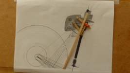
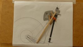
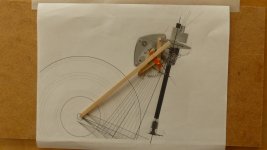
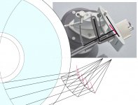
There was something about the Thiele TA01 that caught my attention - an extra part compared to other twin arm PLTs - so I built a model based on Thiele's drawing of the geometry and movement of the arm.
The extra part is the small orange arm, which actually carries the vertical bearings and the wand. Kind of a lot to ask of a small part. In effect, the TA01 seems to have two control arms making it a three-arm PLT and the third arm is probably the critical factor. If so, it's an interesting contribution to Birch-based design.
The drawing is cluttered and not particularly accurate, possibly deliberately, but I think I got the important parts and the model followed tangency quite well.
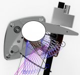
One part of the drawing seemed to reveal something worth checking out. Thiele is claiming zero tracking error, which usually indicates an ellipse segment somewhere. The track of one corner of the vertical bearing/wand carrier was fairly clear and looked like it might show that ellipse so I parked an oval there. I'm not entirely convinced, but the fit looks pretty good to me.
The extra part is the small orange arm, which actually carries the vertical bearings and the wand. Kind of a lot to ask of a small part. In effect, the TA01 seems to have two control arms making it a three-arm PLT and the third arm is probably the critical factor. If so, it's an interesting contribution to Birch-based design.
The drawing is cluttered and not particularly accurate, possibly deliberately, but I think I got the important parts and the model followed tangency quite well.
One part of the drawing seemed to reveal something worth checking out. Thiele is claiming zero tracking error, which usually indicates an ellipse segment somewhere. The track of one corner of the vertical bearing/wand carrier was fairly clear and looked like it might show that ellipse so I parked an oval there. I'm not entirely convinced, but the fit looks pretty good to me.
Attachments
Last edited:
Hi Doug,
You are right. I modified my original drawing slightly to better reflect TA01 mechanism. In fact, the fundamental principle is still the same, but the implementation is slightly different. Please see my new drawing. The red lines represent your extra link in red. In my opinion, such an extra link is not necessary. I don't think TA01 is following an ellipse at all. I also don't understand why they use two pieces of wood in the link. Isn't aluminum better?
I don't think an ellipse is necessarily more accurate than a circle. There are many parameters that have an effect on tracking errors. The shape of the guide is one of them.
I personally prefer the geometry of Schröder LT tonearm although I found it independently, too. It is simple and elegant without extra links.
Jim
Attachments
Last edited:
IP is in place, so I can share this publicly now.
It is a compound compliant mechanism with inspiration from a Jacob's ladder toy.


Bonus points if anyone can identify the AS mechanism.
c1 - YouTube
This shows a single cam connection, with very low friction, as the cams are not in contact with each other. The only friction can come from a virtual line down the middle of the crossing bands and is pure rolling resistance.
cc - YouTube
In the completed horizontal mechanism, even with the compound mechanism, the friction is low enough that I can see my heart beat because there is zero stiction. There are no bearings and in the completed tonearm there are only 2 very strict DOF, all the other DOF are constrained rigidly by the bands. There are no tangency errors at all during rotation.
I tried to measure the starting torque, but it is too low for my crude device, so will try a micrometer to spin the rod on the next build.
6 years in the making, about 30 iterations and 3 working prototypes.
I'm currently building 2 for a backer (90% done) and will have some in action measurements "soon".
Tonearm is 95 mm from pivot to tip, and the fixed cam pillar is 15 mm radius.
Cue will have to be dreamt up later.
It is a compound compliant mechanism with inspiration from a Jacob's ladder toy.
Bonus points if anyone can identify the AS mechanism.
c1 - YouTube
This shows a single cam connection, with very low friction, as the cams are not in contact with each other. The only friction can come from a virtual line down the middle of the crossing bands and is pure rolling resistance.
cc - YouTube
In the completed horizontal mechanism, even with the compound mechanism, the friction is low enough that I can see my heart beat because there is zero stiction. There are no bearings and in the completed tonearm there are only 2 very strict DOF, all the other DOF are constrained rigidly by the bands. There are no tangency errors at all during rotation.
I tried to measure the starting torque, but it is too low for my crude device, so will try a micrometer to spin the rod on the next build.
6 years in the making, about 30 iterations and 3 working prototypes.
I'm currently building 2 for a backer (90% done) and will have some in action measurements "soon".
Tonearm is 95 mm from pivot to tip, and the fixed cam pillar is 15 mm radius.
Cue will have to be dreamt up later.
A real innovation!
Thank you very much.
2wice,
I still need time to study the mechanism. But it is surely eye-opening and innovative. Congratulations!
One question for now. The arm is 95 mm long. Does that mean there is an additional supporting structure to hover the whole mechanism over the record?
Jim
Nothing, the only thing keeping everything together are the constraint bands. Thank you for your kind words.

Last edited:
Nothing, the only thing keeping everything together are the constraint bands. Thank you for your kind words.
2wice,
Although you were talking about something else, I understand it now. So, what is the thickness of metal bands?
Jim
2wice,
Although you were talking about something else, I understand it now. So, what is the thickness of metal bands?
Jim
50 μm
Peculiar and at the same time very elegant
Anyway, a peculiar looking, but very elegant design-solution. Also because the rotating elements can be non-circular So congratulations for cooking up a very elegant contraption ( ) like this.
Best regards,
Mark
I give up... no idea. Or,, perhaps a small deviation from strictly vertical so that the arm is lifted a wee bit when moving inward (resulting in a small outward-directed force)?Bonus points if anyone can identify the AS mechanism.
I don't agree. The rotating elements with retaining bands / ribbons do effectively form bearings.There are no bearings and in the completed tonearm..
Anyway, a peculiar looking, but very elegant design-solution. Also because the rotating elements can be non-circular
So congratulations for cooking up a very elegant contraption ( ) like this.Best regards,
Mark
- Home
- Source & Line
- Analogue Source
- Angling for 90° - tangential pivot tonearms