I look at the Paradise as a child, a rather perfect one though. It will mature and grow.
I was always very open to criticism. How else can i progress ?
Hear hear

The negative side is : you change the original design and loose the freshness of the first shot. I will not change mine. Lets see what happens when we do the shootout in september.
I am luky as I will have R3 boards to keep as original and the R2 beta boards to play with and compare
Meybe I shuld have got an extra set
I can see next group buy realy soon
Thank you so much.Taking out one 6800uF of each double stack puts the -3dB frequency one octave higher.
They are totally over dimensioned to begin with.
When you build the R3, Ricardo you could leave half of them out at the beginning and listen how that sounds. Soldering the caps out of your R2 boards is of cause possible but some kind of dirty work.
I found that the Lundals are not that sensitive of loading. I would try a 10kOhm loading resistor. That is in my opinion the highest reasonable value. That would load the Tuscany with 50 Ohm. You could even try without any loading resistor. The secondary impedance of the transformer allows a DC biasing path through the input stage so it may amplify.
Good advise... I am now in paradise listening to R2... I would not like to risk any more hot iron on it again.
That is a good position you are in !
What will be really important now is that we focus on helping the people to make their Paradise work, a lot of stupid mistakes can happen.
Happened to me including swapping PNP-NPN and putting in some Leds the opposite way.
Good that Hesener changed the footprint. Things like that can drive you crazy.
Absolutely right
Yes there where a few emails behind the curtains while I was building beta glad that I was able to make small contribution.
Another one was one of capacitor the wrong way around in my build
I did check and dubleduble check but still made that mistake You been warned
Just waiting for build guide maybe it need Proof reading so just PM
One not to be forgotten is: Keep pins on small regulator transistors realy shorth as otherwise they touch the heat sink
Yes, keep them short, happened to me too and then i simply bend them over a bit...
terrible fix...
Ok so that is another one for Guide
Hessener could you send what you have for now so we can chip in.
That happened to me also... I forgotYes, keep them short, happened to me too and then i simply bend them over a bit...
terrible fix...
I corrected it on the second channel.
A build guide will be welcome.
1st.... place all resistors.
1st.... place all NPN
2nd... place all PNP
Be carefull to keep low riding ones beneath the heatsink
3rd.... place diodes and small caps and light emiting diodes (measure all diodes before implanting)
4th.... trimmers
5th.... opamps
6th.... small EL
7th.... heatsink with power trannies
8th.... big EL
This is only a first approach.. should be finetuned with all intervenients opinions and best practices.
PS: Remenber there is need to GND connection in the riaa case for the arm GND wire (unless you use a rega or other thing that uses left channel gnd as arm gnd)
Last edited:
")
For the big ones on cooler
I first fitted the transistors to cooler before welding
One may start form sides or middle fit first one nice and square twiddle in place position the second one take out and clamp repeat till lot is in and then weld
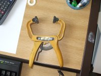
Or, found it after, weld in place transistors and then use magic tool like in picture to clamp
IMO this is the most difficult part of build so take your time as clamps are a pain to get off.
I first fitted the transistors to cooler before welding
One may start form sides or middle fit first one nice and square twiddle in place position the second one take out and clamp repeat till lot is in and then weld
Or, found it after, weld in place transistors and then use magic tool like in picture to clamp
IMO this is the most difficult part of build so take your time as clamps are a pain to get off.
Attachments
Last edited:
For the big ones on cooler
I first fitted the transistors to cooler before welding
One may start form sides or middle fit first one nice and square twiddle in place position the second one take out and clamp repeat till lot is in and then weld
Or, found it after, weld in place transistors and then use magic tool like in picture to clamp
IMO this is the most difficult part of build so take your time as clamps are a pain to get off.
I prefer to lay the power trannies on the heatsink, then fix them with the springs, then point them into the holes, fix the heatsink and finally solder everything in place.