Yes, Martina was the beta tester on many incarnations. Martina has very good technical knowledge of mechanical things. She has repaired my coffee machine, my telephone, debugged my computer, repaired my car and other things. It is only when it comes to electronics she can not follow each and every little detail but i think that is a blessing because she it not very biased in terms of topology. When it does not sound right to her she does not care about the underlying technology ( she cares actually, but i hope you understand what i mean). Martina has also a different way to listen to audio. For example Martina loves classical music and especially older recordings that are sometimes hard to reproduce. Instead of judging the technical excellence she compares the sound of reproduction to the sound of real life music.
She is an expert on the human voice and there was in the beginning where i failed. At first i simply restored to the old garbage in garbage out argument but then we found that the sound of voices can be improved by improving the phono stages. And so it goes..
She is an expert on the human voice and there was in the beginning where i failed. At first i simply restored to the old garbage in garbage out argument but then we found that the sound of voices can be improved by improving the phono stages. And so it goes..
Sure, i worked at Essex University in the early 90th so i got a fair dose of that good poison. Actually the Pro AC Tablette was the speaker that impressed me so much that i founded Audio Physic. I fantasized when something so small can make so much music there must be a customer potential, and i was right.
Martina Danke !
Hi Martina & Joachim,
Now I understand why Joachim is so good in making music sound at it's best through his equipments; he fine tunes his products via Martina's ears
Well I actually do the same thing here, I ask my sweet partner to judge my work and if it's OK she will smile and close her eyes and keep on listening.
Danke Martina, danke Joachim and thanks to all of you who helped to make this thread a big success ! Happy new year to you all.
atb,
José
Audiofanatic
Needs some explanation, I think.
Someone, in a private mail, called the Sziklai pair and capacitor in front of the LM317 current source an capacitor multiplier, and that it is not!
Actually the arrangement is a constant voltage source that supplies the current source, and the reference voltage for this voltage source is the output voltage of the shunt regulator.
This way the voltage supplied to the current source is as stable (about) as the voltage supplied by the shunt, and that voltage is very stable.
In effect this arrangement ‘degrades’ the LM317 to be a ‘mime’ of a resistor, the amount of work it has to do is minimal and the quality of the component is of minimal influence on the quality of the regulator.
Attached an comparison with a ‘standard’ shunt regulator and an enhanced version of the standard shunt regulator.
Anyway I hope you like it.
Someone, in a private mail, called the Sziklai pair and capacitor in front of the LM317 current source an capacitor multiplier
, and that it is not! Actually the arrangement is a constant voltage source that supplies the current source, and the reference voltage for this voltage source is the output voltage of the shunt regulator.
This way the voltage supplied to the current source is as stable (about) as the voltage supplied by the shunt, and that voltage is very stable.
In effect this arrangement ‘degrades’ the LM317 to be a ‘mime’ of a resistor, the amount of work it has to do is minimal and the quality of the component is of minimal influence on the quality of the regulator.
Attached an comparison with a ‘standard’ shunt regulator and an enhanced version of the standard shunt regulator.
Anyway I hope you like it.
Attachments
Hello Hesener. Welcome back. I know you are busy.
Frans, thanks for clarifying this.
I asume that the red trace is yours or is it the green trace that has somewhat better hum rejection ?
Yes
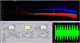
The case shown is a real worst case situation, with 3 volts 333 Khz on the source, and 50 mA amplitude 1 Khz on the load.
In the pane right below, red (straight line) is ours, blue (slightly bumpy) is enhanced (with the voltage source) ‘standard’ and green is ‘standard’ (center schema).
In the FFT pane the red trace has a lower ‘base’ line, but all peeks are about 32 dB up when compared with the green line (our regulator), so I would conclude that the green is about 32 dB better.
For some reason the low frequency part of the FFT is a bit better for the ‘standard’ version.
But if you look at the 30Khz load dependence, you will see that our version is about 32dB better than the ‘standard’ version.
I am still looking into that 120 dB start, as opposed the 160 dB start, of the FFT graph. The only source of low frequency noise is the LED string.
It wins hands down (our version).
Red is the one on the left, green the one in the middle and blue the poor puppy on the right.
If I get this right, the standard 317/431 ist only a little worse than the full blown thing.
But that little is 32 dB in all the peeks that show in the FFT.
P.s. The ripple on the ‘standard’ power supply 12.86mV and on ours is 350uV.
again, ours about 40 times better!
Last edited:
Someone, in a private mail, called the Sziklai pair and capacitor in front of the LM317 current source an capacitor multiplier
Actually the arrangement is a constant voltage source that supplies the current source, and the reference voltage for this voltage source is the output voltage of the shunt regulator.
This way the voltage supplied to the current source is as stable (about) as the voltage supplied by the shunt, and that voltage is very stable.
In effect this arrangement ‘degrades’ the LM317 to be a ‘mime’ of a resistor, the amount of work it has to do is minimal and the quality of the component is of minimal influence on the quality of the regulator.
Attached an comparison with a ‘standard’ shunt regulator and an enhanced version of the standard shunt regulator.
Anyway I hope you like it.
It is incredible the amout of knowledge I am gathering just by following this.
Thank you Frans. Now I have a better understanding how it works. Particularly like the idea to reference the ccs voltage to the output of the shunt.
I noticed that in your previous schematic there is +24V raw in for +24Vout. Does it mean there is no voltage drop in the shunt ?
How much can we raise Vin ?
No, its just the names. The 24Vout is 24Volt (on the meter
)And yes I liked that idea also (maybe my little invention).
Yes, that FFT is stretched out over a VERY wide dynamic range so it fools the eye.
Anyway, i am confident that Frans design will work just fine.
I'm sure it is an stable power supply with an extreme high input noise and load ripple rejection (e.g. an very, very low output impedance).
And the reference could be improved, but I see no reason to do so (really
)The tricky part is, make it simple and make it better (and do not spend 6 million dollar)
Last edited:
Particularly like the idea to reference the ccs voltage to the output of the shunt.
1.2-1.2R CCS anyone?
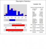
I have only measured 64 BC337 so my findings might not reflect the true picture but I decided to post them anyway. Will post a more acurate picture when I pass the 100 parts count.
I love minitab ... You can see a 95% confidence interval for Median between 462 and 480Hfe, so excluding the outliers we can count with aprox 5% deviation without matching.
There is a slight skewness to the left because I found a big number of parts with 450Hfe.
I decided to match all the transistors because it would be very difficult for me to adjust differences with resistors.
Joachim... Would you suggest the best positions for the several most significative Hfe values I found ?
Now this is all part of the fun: