3) I see no reason why the current mirrors around Q1-8, Q19-22 are so extremely complex.
This could be done with far less components only playing a role for DC.
Hans
Q1-8 form a cascoded current mirror ... the idea is to improve output impedance
Q19-22 form a floating CCS needed to bias the input jfets.
Do you believe we can have better accuracy with a simpler mirror ?
Generally - or theoretically - it may be a good idea to have a VERY large output impedance.
But compare this to complexity, usefulness and also linearity, conflicting demands now and then.
The best example of this is **, loading an "infinite" output impedance with only 221 ohms resistor -
any more questions ? Everything "gained" in a 34 transistor input stage is lost with a low load
like this (and even lower at frequencies above 20 Hz due to RIAA network).
Your RIAA load is 71k and less - if the output impedance is "too low" increase R54 71k.
I have simplified these current sources to a level that seems adequate.Q1-8 cascode was prefered to improved wilson because it also has enhanced output impedance without the feedback
Since they are decoupled by 8000uF caps, I would be more worried about the HF impedance of these caps. The output impedance of the current sources have no effect because of these caps.
The least you should do is to place 100nF caps in parallel.
To get a nice flat Riaa curve, I have increased R64 from 73.5K to 77K.
Output impedance was a measured 42 Ohm from 20Hz to 20KHz, which is perfect.
S/N with a 560mH + 460 Ohm Cart, terminated with 47K + 150pF for the cable capacitance was 79.5 dBA, or the equivalent of 3,76nV/rtHz input noise.
Hans
Attachments
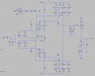
I have simplified these current sources to a level that seems adequate. ...
@Hans, It is known (for a long time now) that it is possible to design a simpler RIAA-pre-amp than this one here in the MPP thread, but this (as it is now) is the cumulative effort (in testing and designing) of many peoples (including myself).
We have been talking about this design, including about the design decision that you refer here (especially the current sources and mirrors), for over 11000 messages, the thing is, this pre-amp designed by Joachim Gerhard is what it is, and if these design decisions need re-discussing then please re-read what has been discussed before, and reference the data as presented in the past.
We discussed current mirrors a lot. Some of them had extremely high output impedance but not so good thermal stability. I think a compromise has to be struck here. That way we arrived at the circuit that is used in the Paradise and be build successful at least 600 times that I know of. I have designed commercial circuits that had even better performance and where still open loop. I think with a lot of care distortion can be brought down by some 20dB, at least in the simulator.
We discussed current mirrors a lot. Some of them had extremely high output impedance but not so good thermal stability. I think a compromise has to be struck here. That way we arrived at the circuit that is used in the Paradise and be build successful at least 600 times that I know of. I have designed commercial circuits that had even better performance and where still open loop. I think with a lot of care distortion can be brought down by some 20dB, at least in the simulator.
As mentioned, I just came across this thread without knowing the history and gave my unbiased comment.
I wish you a continuation of your succes so far.
Hans
Still one last question out of curiousity:
When the circuit presented a few postings before this one is correct, Gain at 1kHz is some 60dB.
Is there a special reason for this.
The usual gain for an MM amp is around 40dB. A Gain of 60dB makes the overload margin some 20dB smaller.
Hans
When the circuit presented a few postings before this one is correct, Gain at 1kHz is some 60dB.
Is there a special reason for this.
The usual gain for an MM amp is around 40dB. A Gain of 60dB makes the overload margin some 20dB smaller.
Hans
It was not designed for MM use.
O.k. that makes sense.
I was falsly triggered by the 47k input resistor.
Hans
It was not designed for MM use.
Not completely true, the origin of this last "incarnation" was due to a request
to convert a given topology for mm use.
See post 10952 and following.
The 'Paradise RIAA Pre-Amp' is designed for MC, the adaptation presented in the last few messages is to make it useable for MM (not designed for MM), this was just done (as seen by me) out of curiosity and in response to a question of one of the respondents (sorry Ricardo your now a respondent ") ).
).
).Hi HansI have simplified these current sources to a level that seems adequate.
Since they are decoupled by 8000uF caps, I would be more worried about the HF impedance of these caps. The output impedance of the current sources have no effect because of these caps.
The least you should do is to place 100nF caps in parallel.
To get a nice flat Riaa curve, I have increased R64 from 73.5K to 77K.
Output impedance was a measured 42 Ohm from 20Hz to 20KHz, which is perfect.
S/N with a 560mH + 460 Ohm Cart, terminated with 47K + 150pF for the cable capacitance was 79.5 dBA, or the equivalent of 3,76nV/rtHz input noise.
Hans
Thank you for your work that helped getting this new "incarnation" right.
Initially I intended to make a MM preamp so I needed jfet inputs but than I further developed the design to have more gain so to be able to use it with MC carts. 60dB is good and 63dB would be perfect.
I like the simplicity of your wilson mirror and resistive ccs but as you read before, the more complex approach was determined by universal consensus.
I am not sure the resistive ccs can cope well with the servo input... maybe you could add some ideas there.
As for the "flat" riaa curve, indeed the riaa values I left on this "incarnation" where calculated for the original paradise that does not have the special "current amplifying" mirror.
With this new mirror that amplifies current (needed because I wanted more gain) the riaa loading resistor must indeed be increased.
Now comes the interesting part:
How did you determine the 77k value ?
How did you calculate the "flat" riaa... did you use an inverse riaa at the input ?
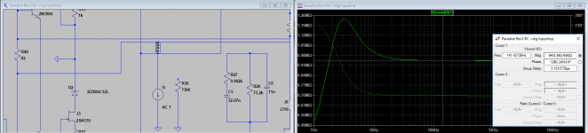
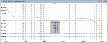
In the initial paradise development I studied the RIAA filter and found the RIAA node impedance to be around 940kohm
With that value, the loading resistor should be near 73k so to cope with SL calc
73k // 940k <> 68149
With that value, the loading resistor should be near 73k so to cope with SL calc
73k // 940k <> 68149
Attachments
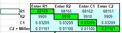
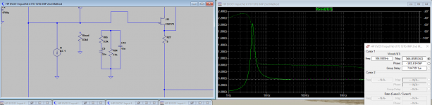
Now back to the jfet IPS implementation, acording to my sim RIAA node impedance is around 366k so to have the correct large resistor in the RIAA filter around 68k, I would need 83k8 instead of 77k you posted.... your comments will be most helpfull so I can confirm my sim method.
Attachments
In this reincarnation, the amp is extremely useable for MC cart's with only 0.29nV/rtHz with a 10 Ohm cart connected (81.7 dBA S/N ref 0.5mV)Hi Hans
Initially I intended to make a MM preamp so I needed jfet inputs but than I further developed the design to have more gain so to be able to use it with MC carts. 60dB is good and 63dB would be perfect.
I don't know the arguments for using the more complex version, which of course I fully respect, but thermal stability, output impedance (8000uF !) or functioning of the servo could hardly be a reason as can be easily simulated.I like the simplicity of your wilson mirror and resistive ccs but as you read before, the more complex approach was determined by universal consensus.
I am not sure the resistive ccs can cope well with the servo input... maybe you could add some ideas there.
Correct, I didn't calculate anything at all, I simply used an inverse Riaa signal at the input.As for the "flat" riaa curve, indeed the riaa values I left on this "incarnation" where calculated for the original paradise that does not have the special "current amplifying" mirror.
How did you determine the 77k value ?
How did you calculate the "flat" riaa... did you use an inverse riaa at the input ?
Hans
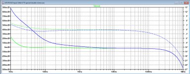
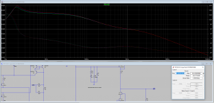
Here is the response with 77K with anti Riaa input
Hans
Thank you Hans.... would you post this same curve with 83k8 ?
Green is 77K, Blue 83k8Thank you Hans.... would you post this same curve with 83k8 ?