I worked with Hawksford. I would be very interested to see your power amp.
I will not post my amp here for now, there is some exemples of the hawksford error correction (HEC) already online , Bob Cordell have a mosfet amplifier with HEC. And Jan Didden´s have the pax amplifier. And also the Dr. hawksford paper:
http://linearaudio.nl/linearaudio.nl/images/pdf/hawksf ec.pdf
My implementation of the HEC is a little different, but in the end the results are similar.
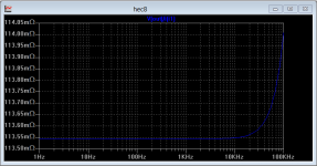
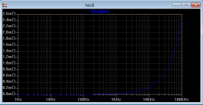
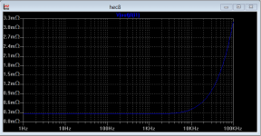
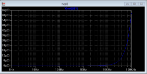
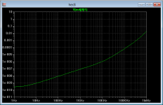
But I will post some graphs than can ilustrate the benefits of hawksford error correction .
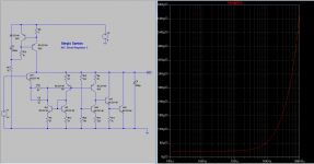
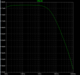
the graphs are the simulated measurement of the output impedance of the power stage of the amplifier.
1- NO feedback and No HEC
2- with feedback only
3- with HEC only
4- with feedback and HEC
Attachments
It is kind of strange that Malkolms idea did not lift off the ground commercially.
The only company that used that principle in quantity is Meridian.
Not even Dr. Bews from LFD is using it.
I have parts for a PAX but i never finished it.
Jan is working on a new version.
The only company that used that principle in quantity is Meridian.
Not even Dr. Bews from LFD is using it.
I have parts for a PAX but i never finished it.
Jan is working on a new version.
In my view the HEC is not used more, because the designers have some difficulty to understand how it works , at least I had. lost a lot of hours looking to the concept.
I think that was Jan that said that he uses the HEC but he dont totally understand how it work.
But widout a doubt Dr. Malkolms is a genius.
I think that was Jan that said that he uses the HEC but he dont totally understand how it work.
But widout a doubt Dr. Malkolms is a genius.
HEC shunt regulator
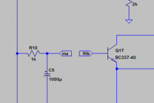
Ok. First attempt to a HEC shunt regulator.
The shunt from the right is equal to the one at left, the only difference is the added connections "INA", "INB" in Q17 base that will connect to the HEC circuit (that I do not show, sorry ). INB is where the error correction current from the HEC will be injected. The HEC circuit is totaly external , so the feedback loop from the original shunt regulator is not affected. My HEC circuit use 8 discrete transistors, no opamps.
Not bad, probably the lowest output impedance regulator on the block.")
Ok. First attempt to a HEC shunt regulator.
The shunt from the right is equal to the one at left, the only difference is the added connections "INA", "INB" in Q17 base that will connect to the HEC circuit (that I do not show, sorry ). INB is where the error correction current from the HEC will be injected. The HEC circuit is totaly external , so the feedback loop from the original shunt regulator is not affected. My HEC circuit use 8 discrete transistors, no opamps.
Not bad, probably the lowest output impedance regulator on the block.
Attachments
Ok. First attempt to a HEC shunt regulator.
The shunt from the right is equal to the one at left, the only difference is the added connections "INA", "INB" in Q17 base that will connect to the HEC circuit (that I do not show, sorry ). INB is where the error correction current from the HEC will be injected. The HEC circuit is totaly external , so the feedback loop from the original shunt regulator is not affected. My HEC circuit use 8 discrete transistors, no opamps.
Not bad, probably the lowest output impedance regulator on the block.
Now show us what is in-between the two labels/connectors
Yes I agree, In practice that can be very hard , if not impossible. ofcourse one can use a sense connection, and that helps to maintain the impedance low.
And I just design this for fun
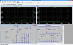
another HEC shunt , based on fig4 of the HEC paper, not the circuit i use in the amp. This time, all the circuit.
This implementation is not very good , but it serves to demonstrate how simple is to implement the HEC.
And I just design this for fun
another HEC shunt , based on fig4 of the HEC paper, not the circuit i use in the amp. This time, all the circuit.
This implementation is not very good , but it serves to demonstrate how simple is to implement the HEC.
Attachments
Now show us what is in-between the two labels/connectors
sorry I will not, hope the last post helps to understand the concept.
HEC shunt regulator 3
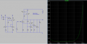
A more practical regulator, the final version will be something like this.
Very good PSRR.
R13 can be tweaked to lower the output impedance , but i like the way it is now.
I think it remains a simple circuit, what you guys think?
A more practical regulator, the final version will be something like this.
Very good PSRR.
R13 can be tweaked to lower the output impedance , but i like the way it is now.
I think it remains a simple circuit, what you guys think?
Attachments
Joachim this is for my ES9018, this dac needs very low power supply impedance so the output voltage is 3,3Volts 100mA.
I also need 12v 100ma for my headphone Amp, but maybe I will use a serial regulator on that, will see if I can use the HEC on a serial regulator too. If I do, I let you know.
I will design a +12/-12 shunt based on this but not today.
I also need 12v 100ma for my headphone Amp, but maybe I will use a serial regulator on that, will see if I can use the HEC on a serial regulator too. If I do, I let you know.
I will design a +12/-12 shunt based on this but not today.
Last edited:
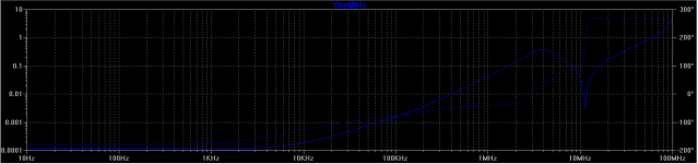
That is along the lines of what I was messing with, but here's the problem. When you lower the output inductance below that that the output device would normally have, you necessarily get a circuit which amplifies RF resonances and is intolerant of series resonances. Why don't you plot output impedance on a decibel scale including phase, to at least 100MHz?
Also look at this. How does it compare to your circuit?
http://www.diyaudio.com/forums/power-supplies/153715-my-take-discrete-shunt-voltage-regulator.html
http://www.diyaudio.com/forums/power-supplies/153715-my-take-discrete-shunt-voltage-regulator.html
Also look at this. How does it compare to your circuit?
http://www.diyaudio.com/forums/power-supplies/153715-my-take-discrete-shunt-voltage-regulator.html
I do not see great similarities, apart from the fact that both are shunt regulators.
I see Zout at 100KHz has risen to 2mR.
Is the current source oriented properly? It should be pointing into the output of the regulator, not out, otherwise your impedance will be measured negative, or phase shifted 180 degrees.
Are you sure it's not oscillating? Your transient sim command, from what I gather from the schematics you don't banish it from, has the minimum timestep set at 1mS. This is like setting a sampling scope to a 1KHz samplerate. Try setting it to 10nS or so and the current source to 1MHz at 10mA and see if you get oscillation. Also add this:
.options plotwinsize=0
I do not see great similarities, apart from the fact that both are shunt regulators.
They are similar in the level of performance they offer. Iko's circuit has been built and tested. Iko's reg doesn't use EC. Compare and contrast, as a learning exercise if nothing else.