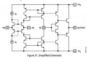
One thing to watch is that the positive
input is not too low in input impedance. There are other input structures. For example imagine that you put a diamond buffer ( like the output buffer in the sketch ) at the input too. The input impedance of the positive input would then be much higher then the input impedance of the negative input.
input is not too low in input impedance. There are other input structures. For example imagine that you put a diamond buffer ( like the output buffer in the sketch ) at the input too. The input impedance of the positive input would then be much higher then the input impedance of the negative input.
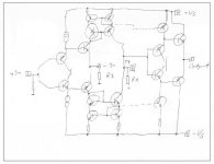
Here is a Transimpedance Line Stage with higher input impedance on the positive input.
Sorry for the poor drawing. I am in semi vacation the next two weeks. The task is to switch off the head. I have reached only 50% efficiency at the moment but i have switched from full Class A into heavy Class AB.")
Sorry for the poor drawing. I am in semi vacation the next two weeks. The task is to switch off the head. I have reached only 50% efficiency at the moment but i have switched from full Class A into heavy Class AB.
Attachments
While we where talking Opamps for audio i found some advice that is very reasonable :http://hifisonix.com/wordpress/wp-content/uploads/2010/10/Opamp-User-Guide-V1.0.pdf

and we are free to choose the one or the other. I hope this clears it up
For example, by putting three parallel 33nF Siemens polystyrene in one channel, and two 33nF EMZ polypropylene and one styroflex in the other, instead of twice 2KS+1KP.
(only kidding, Mr de Wit)
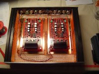
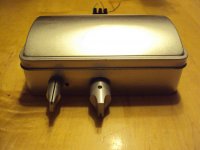
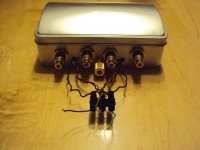
Mr Hesener, really beautiful with the copper plate and foil lining.
To please the Mrs, you could do a wallpaper renewal and blend-in the phono stage with the walls.
=> http://efpro.org/fileadmin/PTS/EFPRO/Dokumente/Workshop_DeBarros.pdf
For example, by putting three parallel 33nF Siemens polystyrene in one channel, and two 33nF EMZ polypropylene and one styroflex in the other, instead of twice 2KS+1KP.
Is'nt there a law against that? if not then we need to make one! People doing these kind of things should be banned from the forum. The people at the ATL let me know 'People ng tese knd tngs sould be bnned from te forum '
F
Mr Hesener, really beautiful with the copper plate and foil lining.
[/url]
thanks for the flowers! after all the metal drilling and stuff over the years, I am now building my cases from wood, and lining with copper foil, only the frontplates are made to order (frontpanelexpress.com). guess that "optimization" has led to the large number of 90% finished hifi gear standing around in my home.... ;-(
They come faster that i can track the web :Liberty Audio - Advanced Stereophile Components at Bottom-line Value Pricing
This phono stage just got an excellent review in Sterophile. It is an all Fet discrete design, seems to be inspired by Borbely.
The interesting thing is that two phonos can be combined for differential balanced.
Now that Sampler is back there is a chance that when the Paradise is done we look into a balanced phono too.
By the way, sales of vinyl is up again in Germany this year, several years in a row. Even the mighty "Stern" was obliged to publish this in the newest issue.
I finished the RIAA part of the Klonika. I may be in semi vacation but this took only the better part of 2 hours. My family is away over the weekend and i got bored. I build the servo version and it worked right away. Yes, building with Opamps is fun !
It usually works without much debugging provided it is not miss wired.
What started as a quick experiment is now a decent phono stage. Thanks Frans, for suggesting the input stage. Again, hum is zero and S/N is more then ok but that can be bettered of cause.
The sound ?
It is too early to tell but the sound is more of the "controlled" variant but not sharp. I would say it sounds even slightly less open in the treble that i am used too. That has to do with running in maybe so it needs some more time on the juice.
What is obvious is the quality of the bass. It is very controlled and clear but also very dynamic if not that "big" and "bold". I have to say that i use the updated Calderas. They are closed boxes and lack the ultimate extension that my active woofer has so take this with a grain of salt.
My P-P build is not that compact as i hoped for but an SMD version of this should not be bigger then a matchbox.
Attachments
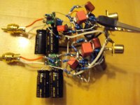
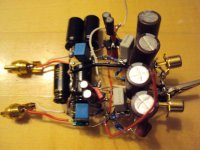
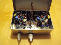
jim williams of LT fame used to build circuits that were quite similar, all parts hanging in the air, like little electronic sculptures. even using digital displays, for thermometers and such. i just love the looks...
just back from a listening session, paradise says hello and is doing just fine. the modification of the current mirrors that you did actually took away some of that "in-your-face" sound, they have the same precision and atmosphere as before but the aggressiveness is gone. the imaging is more homogenous now, whereas before the individual sound events were sticking out a little too much. very nice.....
have received your boards, they will undergo the "treatment" once i find that bag with the SMD caps again ;-)
Thanks, that you like my little sculptures. The interesting thing is that P-P circuits like this work very well whereas putting them on a PCB can cause trouble. As chaotic as it looks, in some ways this is the best way to do. My friends of Lyra in Japan made even an art form out of this but their 3-Ds look of cause much more well ordered.
Good, that you like the modification. I found it sounded also more dynamic but every system is different. Could you do me a favor and rewire the mirrors too to the new circuit ? I can do that too but i thought when you are at it anyway it would safe some time, of cause mine !
Good, that you like the modification. I found it sounded also more dynamic but every system is different. Could you do me a favor and rewire the mirrors too to the new circuit ? I can do that too but i thought when you are at it anyway it would safe some time, of cause mine !
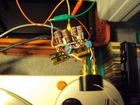
I also build a P-P of the High Speed Preamp Marcin is working on. Do not worry, i did not break the vacation today. I even drove to town with my bicycle to buy some food ( 10km ). This is an older build that will be used in Holger Barskes solar powered system on the Frickelfest.
I "limited" the frequency response to 25MHz so this is really damn fast. Marcins version will even reach higher and we have included a variable Class A bias.
I "limited" the frequency response to 25MHz so this is really damn fast. Marcins version will even reach higher and we have included a variable Class A bias.
Attachments
I am thru SMT soldering of High Speed Pre, except for one additional cap and feedback resistors which are on delivery to me.
I hope the newborn will let me solder thru hole elements tonite'..
What I can say working with the big MELF's is just a pleasure! Fast, clean, no leads bending needed.
I hope the newborn will let me solder thru hole elements tonite'..
What I can say working with the big MELF's is just a pleasure! Fast, clean, no leads bending needed.