Yes averaging can lower dynamic resolution but only to a certain point.
0.3nVqHz seems to be the boundary at the moment at least at room temperature with silizium transistors
one posibility whould be gallium-arsenide cooled down low maybe with a peltier element
but the -140dB/U i get consistently with a variety of designs is quiet enough for me.
if an ultra low noise design whould sound any better is open to debate anyway.
i am not a great layouter so this work is done by another person for me.
he is so good that i get tears in my eyes.
of cause the physical properties of the pcb material have an influence.
for best sound in low level circuits i prefer air dialectric construction but there is very good pcb material availlable say from teflon or other composures albeit at a premium.
i do not have enough experience with different materials but listeng tests (and measurements) of the same circuit on different materials are on the agenda.
Very interesting design - thank you very much indeed for puplishing it. Allow me a couple of stupid questions: What is the impedance of the input stage as shown and how much AC gain does it have (or what range can it have)?
By the way, I vagely remember a review of a phonostage from Audio Physic in a German hifi magazine many moons ago - it was highly appraised. Is this by any chance similar to the current design? I seem to remember some mentioning of a transimpedance stage or somthing of the kind.
By the way, I vagely remember a review of a phonostage from Audio Physic in a German hifi magazine many moons ago - it was highly appraised. Is this by any chance similar to the current design? I seem to remember some mentioning of a transimpedance stage or somthing of the kind.
The gain of the input stage alone is x20 plus x3 from the first stage of the Intrumentation amp without the 318usec and 3180usec RIAA in place with a cardridge of 5 Ohm impedance. the measurements i have shown here reflect that situation. So gain is 36dB.
it is 10dB higher then the Paris that has 26dB. So in praxis you do not have to crank the volume as much as with the Paris winning some gain in noise performance. The second stage of the Instrumentation amp will ad 24dB of gain at 1kHZ and 44dB of gain in the bass region to total gain is 60dB with compleet RIAA in place. This can easyly be changed (raised) by lowering R8 ore/and lowering R11,12 in equal measure.
In fact if i whould do the circuit all over again i whould distribute the gain between the input stage of the instumenation amp and the differential output stage more evenly to unburden the outputstage. With 24dB of gain at frequencies of 1kHz and higher the frequency response of the last stage is still several MHz because i use an OPamp with exeptionally high Gain-Bandwidth product but distributing the gain more evenly whould result in similar speed and distortion in both stages. The reason i came to this dimentioning was that i did not have the right value resistors on hand when i build the prototype. Still the contribution of the Intrumentation amp to distortion is very little. Most distortion comes from the input stage that has no voltage feedback so i wil give that stage more attention too.
Concerning the Audio Physic Phonostage it was a transimpedance design too but single ended not balanced and not parallel symmetric. The sound of that stage is still good today excelling in distiguished handling of dynamics. The problem of that stage was that it had automatic trigering and needed an impuls to switch on for example when you lower the cardridje to the record. With very low output cardridges like for example the Jan Allerts it could happen that it switched of in soft pasages giving rise to a lot of frustration by some users. the reason for that decision was the way we handled the battery supply. We did not want that the circuitry could be left on in case you forgot to switch it off to give the batteries more usefull life. some kind of weak KI, it was quite tempramental.
Input impedance : i run the input transistors of the MPP prototype on 2.6mA giving a dynamic input impedance of some 230 Ohms on both legs. So the plus input has 230 Ohm to ground and the minus input has 230 Ohm to ground dynamically. this does not reflect the noiseimpedance that is somewhat (much) lower at ca 30 Ohm. Shunting the bias transistors with 2200uF electrolytics halfs that values and gives a noiseadvantage of 3dB. I am just building the other channel with that option to compare. I use very good polymer electrolytics with only 8 milli ohms impedance at 100kHz so i hope they do no harm.
To syn08 and others that may be concerned about dumping current into the cardridge.
The MPP does not do that much because it is symmetrical and uses PNP and NPN types in equal measure on both inputs. yes i know the MAT03 has much less current gain but that is not a real problem in this design.
by the way i will try to advance the bias current to maybe 3.5mA. The MAT02 hits the sweetspot at 3mA but the MAT03 likes some more. I will optimise and discuss the bias currents during this thread in more detail.
More information i have gathered about dumping current into the cardridge : the generator will be pushed out of the middle position a bit not much different from raising the downpreasure. So second harmonic rises because that is an asymmetric distortion making the sound a bit more "full and heavy". Lowering the downpresure a bit can compensate for that giving a slightly lighter balance. I adjust downpreasure by ear anyway at least the microadjustment after i have reached satifying measurements.
RIAA and alternative second gainstage
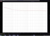
I post a measurement of the RIAA curve i got from the prototype.
It shows a resolution of 1dB. The 1dB error at 20 Hz is due to the fact that i did not have a 318kOhm resistor around and used 3 parrallel 1MegOhm instead so this is easy to avoid. The result shows that the basic mathematics are correct.
As promissed i show also 2 alternative discreet circuits that can be used in case you do not like opamps in the signal chain. They contain the 318usec and 318ousec timeconstans implemented again as a transimpedance circuit.
They do the same job as the Intrumentation amp (actually not because they are conceptually much simpler) and are balanced in and out.
They can be further improved by bootstrapping so can the inputstage. i am not a great bootstrapper so ideas are very wellcome. i understand the basic idea but actually i never used that concept.
Thoose cicuits have to be finished of with two seperate unity gain buffers so one of my nexts post will show some options in various states of perfection and sofistication.
Next time i will send you measurements of the finished MPP prototype included the second and third time constants in full monty.
Attachments
It occurred to me that two buffers are not needed if the output has not to be balanced two buffers would have an offset that needs additional attention if coupling capacitors are not on the wish list.
See my diagram where the Fet gain stage is finished of with a diamond buffer Hawksford style and a servo. I do not yet know where to connect the servo ideally. Give me some time.
When you look at the buffer it has a twist that the collectors of the input transistors are not connected to the power supply but to the emitters of the output transistors giving better performance with minimal complication. This is very typical for Malkolms thinking. Consider also that this circuit is over 20 years old. I had not even heard about a diamond buffer at that time.
Attachments
Simple Buffer
Here are some simple use full buffers. The next post will show some more advanced circuits.
Performance of those circuits can be surprisingly good in terms of bandwidth
and distortion though they need a good power supply.
For the OP amp buffer i would use a current feedback design. They have better drive and speed then voltage feedback designs.
Be shure to use the correct value feedback resistor because stability in a current feedback OP is dependent on that resistor.
A short circuit from output to pin 2 does not work here.
Attachments
I find your design very intriguing and I am surprised that you do not get much response. People are either scared off or the title plus the low number of visitors on this particular forum are the reason for this.
In the latter case may I suggest a little marketing and to use Syn08's approach of intentionally posting a design in the wrong but much more frequented Solid State forum")
In the latter case may I suggest a little marketing and to use Syn08's approach of intentionally posting a design in the wrong but much more frequented Solid State forum
Today i fished the second channel and was able to measure it and listen breefly.
I work late hours so everybody at home was sleeping when i came home so i could only listen at low volume to a diet of Casandra Wilson and Diana Krall.
Measurements first:
There are diffences between the channels but most of them can be explained.
One channel (the new one) has 0.8dB more gain. that may come from the MAT02/MAT03 being different on the channels. I had selected the cascode transistors for hfe but could not do that for the MAT´s. I am using a PEAK Consult transitor tester for this and the revers bias diodes in the MAT`s fooled the PEAK. I could of cause measure the hfe directly but i was to lazy. I may change to other input transistors anyway. The gain difference can of cause be adjusted by R7.
The RIAA on that channel had a 1dB loss at 20Hz. That can be expained by the use of poorly matched 10% carbon resistors. The servo is also a bit different in the new channel and has a series resistor of 1Mohm instead of 750kOhm on the first channel. That does not explain the difference because in both servos the brakepoint is very low.
I used a 0.47uF MKT on both channels. Help !!! i am running out of resistors !!!!!
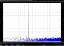
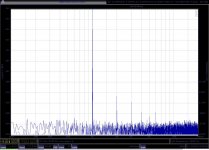
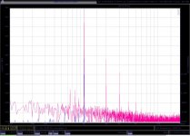
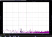
I also put C6, C7, C8 and C9 into the new circuit (value 2200uF) and that lowered distortion a lot. 3rd went under -100dB at 0dB/U output (aka 1V RMS) and 2nd went down from -75dB to -90dB so this modification is recommended. it also lowers the noisefloor somewhat by a theoretical -3dB.
I then mounted some capacitors also in the older channel and got an improovement too but 10dB less on the 2nd and 4dB less on the third then i got on the new channel. higher harmonics (4th, 5th) are also present but very low in value.
i can only explain that behaviour in the context that i used different types of electrolytics. The new channel has SMD polymer Nichicon 6V and the other channel has through hole Nicicon polymer 4V. Why they behave so different i do not know. This part of the circuit is very sensitive to biasing issues so i will try other caps too. One thing that occured to me is that polymer electrolytics of that high value have a very high leakage current in the order of 1mA. Elna and others are making low leakage types that have less then one muA. Wet tantal whould be ideal in that sense although they do no have particalar low ESR. Unfortunately the 2200uF i found from Kemet at Farnell cost a staggering 300,- € each !
Sound :
i listed to Casandra Wilson and Diana Krall at low volume.
The MPP certainly works and what comes out resembles music.
High frequency noise is very low but there was some noise in the deeper ranges that sounded like distant firecrackers. Not objectionable in the listening seet but something to worry about. The circuit is really starving on that primitive powersupply and i will try a well regulated active supply on the weekend.
I had some strage clicking noise on the right channel when i changes volume but in the lab the DC offset of both cannels was under 0.1V.
Maybe my tubeamps are giving up after long use. I already experienced some problems with focus and soudstaging with my fully developped reference phonostage. I use the Goldstandart as Pre-Pre and the MM stage of the soon to be released Quantummusic Telepath phonostage.
Be it as it may, on this weekend i am on the Klangbilder High End Show in the Hilton Danube in Vienna and will play the prototype of the MPP after hours. The Goldstandart, The Hypnosis and The Telepath are also playing.
I hope to take home my repaired and updated Mace Amp to do some more tests when i am home.
I work late hours so everybody at home was sleeping when i came home so i could only listen at low volume to a diet of Casandra Wilson and Diana Krall.
Measurements first:
There are diffences between the channels but most of them can be explained.
One channel (the new one) has 0.8dB more gain. that may come from the MAT02/MAT03 being different on the channels. I had selected the cascode transistors for hfe but could not do that for the MAT´s. I am using a PEAK Consult transitor tester for this and the revers bias diodes in the MAT`s fooled the PEAK. I could of cause measure the hfe directly but i was to lazy. I may change to other input transistors anyway. The gain difference can of cause be adjusted by R7.
The RIAA on that channel had a 1dB loss at 20Hz. That can be expained by the use of poorly matched 10% carbon resistors. The servo is also a bit different in the new channel and has a series resistor of 1Mohm instead of 750kOhm on the first channel. That does not explain the difference because in both servos the brakepoint is very low.
I used a 0.47uF MKT on both channels. Help !!! i am running out of resistors !!!!!
I also put C6, C7, C8 and C9 into the new circuit (value 2200uF) and that lowered distortion a lot. 3rd went under -100dB at 0dB/U output (aka 1V RMS) and 2nd went down from -75dB to -90dB so this modification is recommended. it also lowers the noisefloor somewhat by a theoretical -3dB.
I then mounted some capacitors also in the older channel and got an improovement too but 10dB less on the 2nd and 4dB less on the third then i got on the new channel. higher harmonics (4th, 5th) are also present but very low in value.
i can only explain that behaviour in the context that i used different types of electrolytics. The new channel has SMD polymer Nichicon 6V and the other channel has through hole Nicicon polymer 4V. Why they behave so different i do not know. This part of the circuit is very sensitive to biasing issues so i will try other caps too. One thing that occured to me is that polymer electrolytics of that high value have a very high leakage current in the order of 1mA. Elna and others are making low leakage types that have less then one muA. Wet tantal whould be ideal in that sense although they do no have particalar low ESR. Unfortunately the 2200uF i found from Kemet at Farnell cost a staggering 300,- € each !
Sound :
i listed to Casandra Wilson and Diana Krall at low volume.
The MPP certainly works and what comes out resembles music.
High frequency noise is very low but there was some noise in the deeper ranges that sounded like distant firecrackers. Not objectionable in the listening seet but something to worry about. The circuit is really starving on that primitive powersupply and i will try a well regulated active supply on the weekend.
I had some strage clicking noise on the right channel when i changes volume but in the lab the DC offset of both cannels was under 0.1V.
Maybe my tubeamps are giving up after long use. I already experienced some problems with focus and soudstaging with my fully developped reference phonostage. I use the Goldstandart as Pre-Pre and the MM stage of the soon to be released Quantummusic Telepath phonostage.
Be it as it may, on this weekend i am on the Klangbilder High End Show in the Hilton Danube in Vienna and will play the prototype of the MPP after hours. The Goldstandart, The Hypnosis and The Telepath are also playing.
I hope to take home my repaired and updated Mace Amp to do some more tests when i am home.
Hi MRupp !
i do not care at that moment if this particular thread gets a lot of attention but many thanks that you care.
I will develop it for my own pleasure and hope that it will prosper in terms of quality.
Certainly when the design will be mature i will put it in some quite spectacular casework
with some inovative mechanical solutions that will benefit the sound i hope.
I know how to get attention but this is more like raising a child.
The only thing that disapponts me a bit that nobody is commending on the circuitry so i am on my owm here. i hoped to get some input concerning the optimisation of the topology in terms of speed, noise and distortion. me being trained in the 70th are not so good at simulating but usually a mix of intuition, basic math and experience get´s the job done. Again thank you for your attention.
Hi Joachim,
I think that many of us are reading and learning as you go. Once you have things at a certain level, the questions will begin. So the number of other members posting at this point may be completely irrelevant. There are no metrics that I know of that tell us how many are currently viewing this thread. For example, I've been following, but I'll have to go over everything once more. It's always been late and I don't fully grasp the concepts since I'm tired.
Another distinct possibility, respect. Allowing you to bring your design and ideas forward with no interference from the peanut gallery.
This project / thread should be done for your own enjoyment anyway. Otherwise it's too much like work!
-Chris
This are wise words and actually i have watched a lot of forums before i decided to post here. There are other good ones but this has the nicest tone and highest level of sofistication so i already enjoy what i am doing more then i thought.
I will explain more how the circuit works in detail but eventually it will even get more complex. This is one of the reasons i do not plan to do it as a commercial product. It will simply be extraordinary expensive to make. I am still contemplating how i will make it available if there is any need for it but this is not important at that stage.
So today i post more buffers in various orders of complication (perfection ?) and ad my own design although i never actually build it. but maybe...
Other good ones i found but did not include here because excellent documentation is available are the Borbely and Per-Anders Superbuffers.
Attachments
Before leaving to Vienna i was able to work further on the MPP.
Having prooved that it plays music i was still puzzelt why the two channels are so different. One thing i found was that the bateries on one channel where nearly empty and i had forgotten to do one groundconnection on the new channel. Now both channels work much more similar. They have only a 0.2dB difference in gain now and the RIAA curve is exactly the same with the 1dB of lift at 20Hz i already talked about. Distortion is also the same now until 500mV but a new problem has developped on the new channel. It has more then 3V DC offset and i was sofar not able to cure that. I looked at the servo and other parts of the circuit but i have not found the cause until now.
Anyway i am going to Vienna now where i meet a friend who has the latest generation Audio Precission analyser and is also a very good engineer. I hope we can find some time after hours to repair the new channel. Maybe a component is faulty because i could not find a topology mistake. Stay tuned.
Hi Joachim,
Remember, good technicians and good engineers are never stumped by difficult problems. It's always the very simple things that trip them up. ... from many years observing people.
Have a good time and you don't have to tell us what the problem was.
-Chris
Remember, good technicians and good engineers are never stumped by difficult problems. It's always the very simple things that trip them up. ... from many years observing people.
Have a good time and you don't have to tell us what the problem was.
Thank you! That's the same reason I joined. It's everyone together that makes or breaks a place.There are other good ones but this has the nicest tone and highest level of sofistication so i already enjoy what i am doing more then i thought.
-Chris
Joachim,
Most interesting assessment. Those noise figures are wonderfully low. Your design is most ingenious. I was trained in the sixties, so I know where you are at. That is very good test gear you have, you will be amused to hear one day how I developed the Paris......
Hugh
Most interesting assessment. Those noise figures are wonderfully low. Your design is most ingenious. I was trained in the sixties, so I know where you are at. That is very good test gear you have, you will be amused to hear one day how I developed the Paris......
Hugh
It`a little off topic here because i try to make a transimpedance circuit without NFB in the input stage. On the way to Vienna i designed a voltage feedback version during a break that has voltage feedback and hence less distortion.
I posted it on Syn08`s thread "HPS 4.0 Phonostage " under "Solid State" with more explanation and details.
Anyway here is the basic circuit.
I posted it on Syn08`s thread "HPS 4.0 Phonostage " under "Solid State" with more explanation and details.
Anyway here is the basic circuit.