I wanted to make a comment - and to thank Salas for the design and advice.
I built my valve itch waaaaay back in 2011, pretty much stock build, and I learned a huge amount during the build about grounding and more. Anyway, roll forward years and I've experimented with other phono stages (I can't help it, I'm phonostage curious") ). Anyway, after a period of not using the valve itch I dug it out to try out with a few different turntables I have set up here. I hit an issue where the MC input (vintage partridge step-ups) sounded good, but the MC input was really dull. This really had me scratching my head, and I did a bit of looking around, checking voltages etc to see if something was wrong.
). Anyway, after a period of not using the valve itch I dug it out to try out with a few different turntables I have set up here. I hit an issue where the MC input (vintage partridge step-ups) sounded good, but the MC input was really dull. This really had me scratching my head, and I did a bit of looking around, checking voltages etc to see if something was wrong.
Then I came across this post Valve Itch phono
Which gave me exactly the solution. Right enough, there was higher DC offset than I would like on the inputs. I decided to implement the capacitors on the inputs and everything now is bang on - and it allows me to swap 6n2 easily in the future without testing for optimal grid leak.
Once again, thanks for this fountain of info!
Fran
I built my valve itch waaaaay back in 2011, pretty much stock build, and I learned a huge amount during the build about grounding and more. Anyway, roll forward years and I've experimented with other phono stages (I can't help it, I'm phonostage curious
). Anyway, after a period of not using the valve itch I dug it out to try out with a few different turntables I have set up here. I hit an issue where the MC input (vintage partridge step-ups) sounded good, but the MC input was really dull. This really had me scratching my head, and I did a bit of looking around, checking voltages etc to see if something was wrong. Then I came across this post Valve Itch phono
Which gave me exactly the solution. Right enough, there was higher DC offset than I would like on the inputs. I decided to implement the capacitors on the inputs and everything now is bang on - and it allows me to swap 6n2 easily in the future without testing for optimal grid leak.
Once again, thanks for this fountain of info!
Fran
You are welcome. And nice to hear from you again. You meant the straight MM input sounded dull due to DC offset input bias? 2014 1.2 Itch version has an infrared LED as standard to lift the input tube's cathode a bit for grid current to remain low across tube samples. There is also a rare radiation rated version called 6N2P-ER with even lower grid current spec than 6N2P-EV. And it sounds very good.
Yes, that's it Salas. I should update my knowledge now and look at the newer revision.
In the past, I had only used this with MC carts through the step-ups, and never noticed this issue. Its only because I recently added another deck with a high output MC cart and connected up the MM inputs that I noticed it. At this point I cannot remember if I checked for DC on the inputs way back at the start, but I do know I have swapped around valves a bit over the years, so it is possible that the early ones I used had very low grid leak current.
In any case, I feel a little bit happier now that the carts are protected from DC, no matter what happens with the valve. I also want to go back and see how the sound is now with the MC input, the transformers were obviously dealing with that DC for a while, so it will be interesting to see if there is any difference.
You can calculate grid current of a valve in your now circuit by measuring DC offset across the 47K input load resistor. With no cart or SUT attached. Then solve Ohm's law for current. 0.47V on 47K meaning 10uA leak for instance. Say you managed to bring it down at 47mV by selecting valves and/or lifting with an IR LED. That's a ten fold grid current improvement. 1uA. Surely less problematic. And so on and so forth.
Some 6n2p-er are ordered, we will see if they are real. Seller has good feedback so we will see. I had roughly 0.5V across the 47k resistor....... and yes adding a 1n4148 brought that down to 70mV or so. I still left in the capacitors though, the just give me peace of mind.
I'll report back in time.....
I'll report back in time.....
 Well done up to now. I will be happy to know if they improve leak further in your version and how you like them.
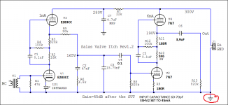
Same B+?
Yes same, try ECC88 that has μ=33. Or some comparable μ spec type. Arrange R9, R10, R11 resistors for about equal voltage across V2 V4 (anode to cathode DC). Around 100V on each. You should gain +6 to +7dB in total.
It is better to be together due to shorter rail cabling. Not as much beneficial as in high current solid state circuits but still preferable. Especially if it is about the SSHV2 low output impedance high voltage shunt regs. The heater regs location does not matter for distance.
Thank you , I have parts arriving soon . Iam working on space requirements in the boxes hence the question . looking forward to the build .
Thanks again
Good luck with the build & enjoy the making worth every moment.
- Home
- Source & Line
- Analogue Source
- Valve Itch phono