First post here, go easy on me, ive been finding this forum a wealth of information.
This is my loricraft/keith monks style record cleaner:
http://www.youtube.com/watch?v=Wqll7_J63G0
Its still very much in prototype phase, but its fully working.
I made most of it myself, i can post further pictures of the details if anyone is interested, they have been posted on a couple of other forums i lurk on.
edd
Here are some pictures at various levels of construction:
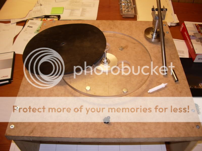
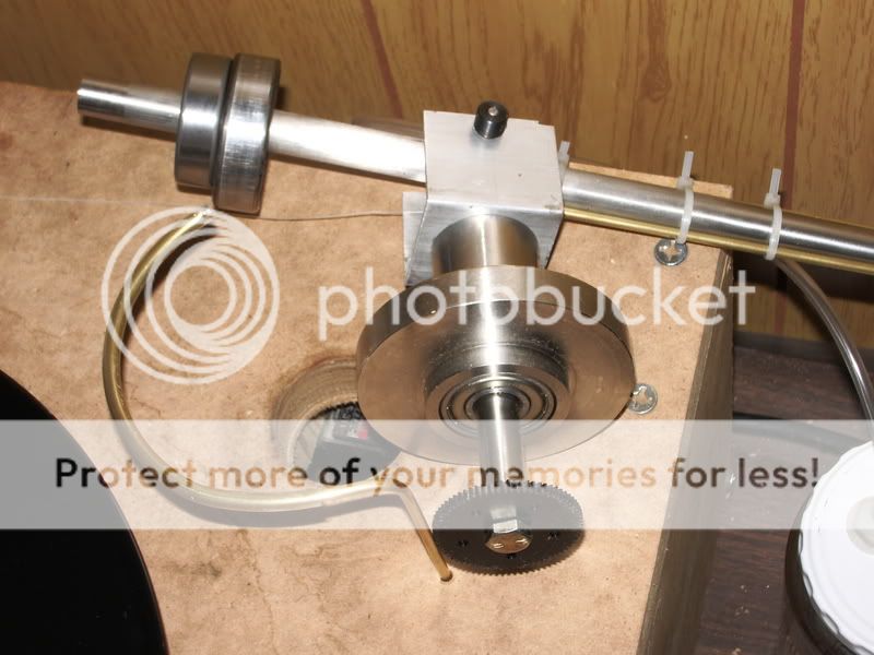
The whole unit. I turned the central bearing housing, spindle and acrylic platter on my lathe.
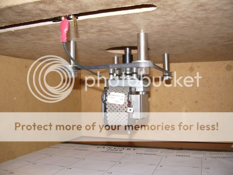
This is the 70rpm gear motor on its mount.
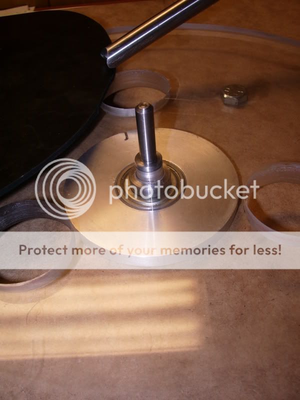
Close up of the central spindle.

This is the teflon nozzle turned from a blank piece of rod stock.
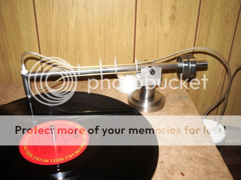
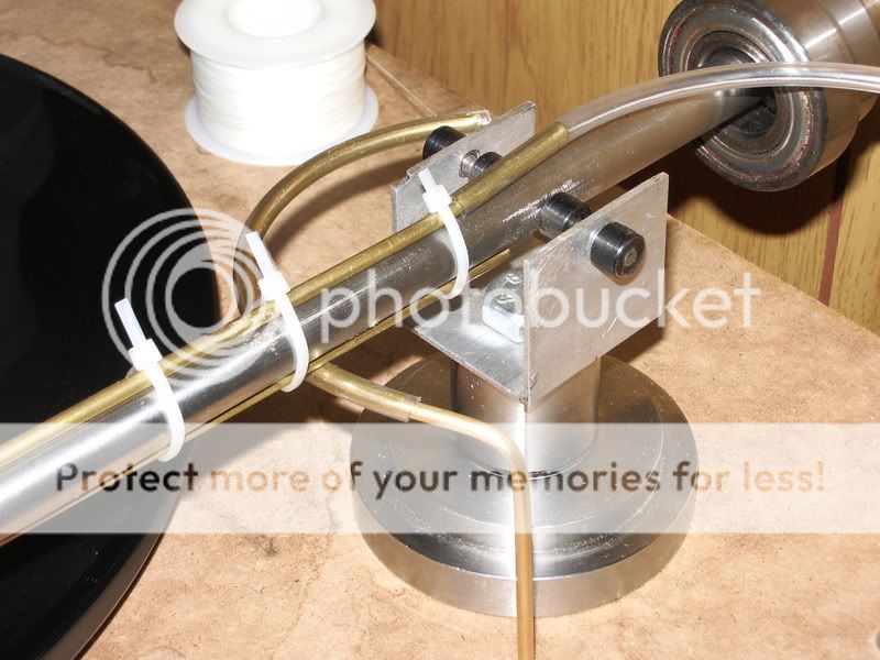
The arm in its current state. I need to solder the brass pipe on rather than use zip ties, but its functional.
"How come that u decided to make it working from inside out??"
no reason, the keith monks works like this. Since the arm is driven from a micro controller, i could make it go either way.
I dont have any pictures of the arm lift or the rotation system yet. Ill take some soon.
Its mostly made of materials i had on hand. The vacuum pump was just something i had spare, its extremely noisy. It should be better when i have a diaphragm pump.
I hope to dress it up in a nice steel topped hardwood box.
edd
The whole unit. I turned the central bearing housing, spindle and acrylic platter on my lathe.
This is the 70rpm gear motor on its mount.
Close up of the central spindle.
This is the teflon nozzle turned from a blank piece of rod stock.
The arm in its current state. I need to solder the brass pipe on rather than use zip ties, but its functional.
"How come that u decided to make it working from inside out??"
no reason, the keith monks works like this. Since the arm is driven from a micro controller, i could make it go either way.
I dont have any pictures of the arm lift or the rotation system yet. Ill take some soon.
Its mostly made of materials i had on hand. The vacuum pump was just something i had spare, its extremely noisy. It should be better when i have a diaphragm pump.
I hope to dress it up in a nice steel topped hardwood box.
edd
Both the keith monks and loricrafts drive the arm across the lp with a small verly low rpm motor. You can see how it works here :
video of keith monks
the arm on the keith monks is driven by a belt, which alows slip so the arm can be possitioned. The loricraft couple the arm to the motor via a magnet.
I didnt realy like either solution. so im using a small microcontroller called the arduino, im using this to automate 2 servos usualy used in rc aircraft, cars etc. The arduino looks for a switch to be thrown, then it cycles the arm.
hope that is clearer.
edd
here are some photos of the arm mechanism.
the arm and lift:
the arm is freely removable (other than the pipe and thread tangle), you can see the gear on the end of the shaft, this has some slip so the arm can be repositioned:
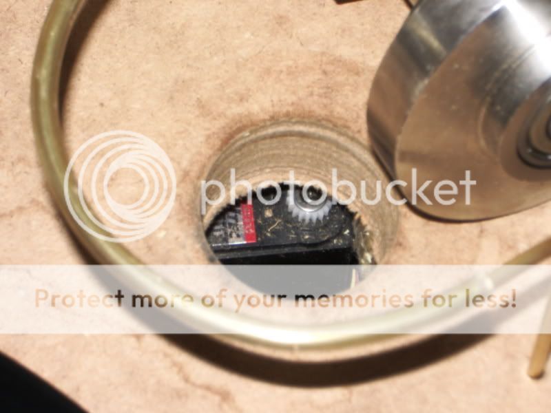
the hole with the driving servo:
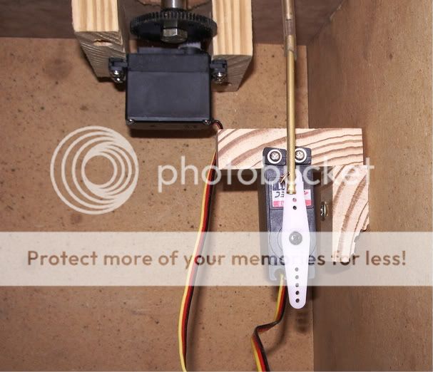
the lift and rotation servos with the basic lift linkage:
edd
the arm and lift:
the arm is freely removable (other than the pipe and thread tangle), you can see the gear on the end of the shaft, this has some slip so the arm can be repositioned:
the hole with the driving servo:
the lift and rotation servos with the basic lift linkage:
edd
nhuwar said:What size of vacuum pump did you use, sounds like a big one?
Nick
The one im testing with is huge, but its designed for high flow low vacuum so as soon as there is any vacuum, the flow plummets. It was just a scrap pump i had in the workshop.
The size to aim for seems to be 0.5-1cfm with 20"hg vacuum, i have just won one on ebay for $55. look for a diaphragm or oilless piston pump.
edd
Cool DIY rig!
Clever rig you've set up Edd! Im a professional Inventor and have the good fortune of having many different parts, components and raw materials in my 22,000 sq ft lab. I also have the machine tools and CAD packages to produce things. I DON'T have the ability to work with or program microcontrollers though!
You say you're using a microcontroller to control the arm, right? If you have any suggestions on that, I'd be interested in knowing what you used and how you programmed it.
For now I'm looking most at the ultrasonic method and may build one of those. Keep up the good work!
Mark in North Caroliina
- Status
- This old topic is closed. If you want to reopen this topic, contact a moderator using the "Report Post" button.
- Home
- Source & Line
- Analogue Source
- My Record cleaning machine