Check out the tuner information center here: http://www.fmtunerinfo.com/
Join their forum and someone should there should be able to answer your question.
Indispensable if you are into collecting, fixing, modifying or building your own tuners..
Join their forum and someone should there should be able to answer your question.
Indispensable if you are into collecting, fixing, modifying or building your own tuners..
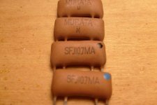
These are old ceramic filters for 10,7 MHz. I used similar filters some 20 years ago, but cannot remember the bandwidth coding.
They are most probably ground referenced, with the two innermost pins connected to ground, but not necessearly internaly connected - try ohming them.
They rely on proper drivind and terminating resistance, and are possibly built for 330 ohms both ways. In/out can be switched , - i.e pin 1 and 4 can be used for input or output at will.
I may have an old Murata catalogue somewhere, but won't have time until X-mas to look for it, as I'm moving house these days and must leave for a 4 week project work on the 15th...sorry.
There are some info here:
http://www.murata.com/av/index.html
Try E-mailing them for further info, or the above referred fmtuner pages may be able to help you.
")
Last time I used something like this they were inner pins ground outer pins specified ~300 Ohms drive impedance. There are narrow band coms versions of these so they might not work for broadcast FM. My DIY tuner was great. I had a friend order the front end as a replacement part from Heathkit, wired up an IF with two of these and used the RCA (????) demod with the MOTO stereo chip. Sort of equaled anything around at a reasonable price.
I forgot, I ordered an early sample of the first Fairchild TTL 100MHz divider (1W!) and some fancy LED displays and hardwired a -10.7 digital circuit. It worked great except for the digital crosstalk blocking several channels.
I forgot, I ordered an early sample of the first Fairchild TTL 100MHz divider (1W!) and some fancy LED displays and hardwired a -10.7 digital circuit. It worked great except for the digital crosstalk blocking several channels.
- Status
- This old topic is closed. If you want to reopen this topic, contact a moderator using the "Report Post" button.