 A dozen posts move here from this thread:
I changed the K117, measured fine before power up.
After power up, all K117 mentioned dead again.
I suspect problem with IRF9530 & IRF9610.
Tried to measure RDS, got some readings but its in the circuit so no sure what to expect because I saw my DMM resistance going up/down (charging capacitor, C2X & C1X?).
Can I try to follow the following guide to test them in circuit?
How to test Mosfet with Multimeter?
Ch1 Q7 most likely gone or there is some problem at its solder joints. Q3x Q5x measured at 77 Ohm RDS is reasonable.
Ch2 Q3x Q5x suspects yes, remove them to confirm RDS & IDSS, but before that see if Q6x is the reason. Measure its VDS. 3-4 VDC is normal. Confirm R3x's value also.
Hello guys, I need some help in troubleshooting in my 2015 FSP.
I have done the below and my analysis.
Please let me know on any other suggestions on where to check? Or possibility on other problems?
Only Q1 is populated, aiming for ~57db gain
Ch1
Only d1-4 no light
Q7 ds resistance is 17ohm
Q3x & Q5x, ds resistance is 77ohm
Q4x vbe is 0.79
Rail and input dc is 44v & 38v.
Between Tp1 & tp2 is -0.07v
- Suspect K117 at Q7 is gone, thus D1-4 not lighted and thus cannot bias and seeing TP1/2 voltage above.
Puzzling ch2
Input 51v
Rail is 22v, cannot be adjusted via VR2x
All leds lights
Bias between Tp 1 & tp2 can adjust to 3-4 via VR2x and VR1
Q3x & Q5x, ds resistance is 15ohm
Q4x vbe is 0.79
Q1x warmer than q6x
- Suspect K117 at Q3x & Q5x is gone thus Rail voltage got stuck.
You have to lift them off. Only reliable test for MOSFETS in circuit is if they develop healthy Vgs DC voltage (DC between pins 1 & 3). At the mA level of this circuit those MOSFET types should show 3-4V Vgs when healthily conducting.
* Maybe the K117 aren't genuine and don't hold at the working voltage?
* Maybe the K117 aren't genuine and don't hold at the working voltage?
The 9610 is possible to show more than 3-4V because weaker in current spec than the 9530. Has to open the gate more to conduct at same level. In more recent years build reports as the stronger IDSS K117GR samples slowly depleted, the rail output adjustment range got difficult to top out and the R3x needed to compensate with higher value around 10k. But that depends on your particular samples.
Hello Salas,
I am at a loss
Replaced all k117 and 9530.
Measures all ok before mounting.
Upon power up.
Input and between rail/gnd measures the same, around 9v.
Both channels d1-4 no light.
Both channels K117 at regulator dead
Both channels 9530 Vgs is zero, Vds same as input.
What could have caused this catastrophic?
R3x being 6.1k?
Last edited:
What could have caused this catastrophic?
R3x being 6.1k?
No way its about Rx. K117s never burned before as a pattern of failure. As Tea wrote check all other semiconductors also.
But measure the raw PSU's output when loaded for 100mA. 470 Ohm 5W dummy load resistors will do.
Finally got home from long absence and managed to test RAW with dummy load. With 470 ohm voltage is down to 46VDC. Its that ok?
I have a unique setup I'm going for and have a question about the SSLV provided on the boards. These are the ultrafsp black boards. I'm planning on utilizing the ultrafsp for a tape head preamp. I will be using a signal channel for NAB and a signal channel for IEC eq. So there will be two signal boards per channel with the unused one having its input grounded. My question is can I use a singal sslv to power both boards on a channel. That is, 1 of the sslvs and 2 signal boards for left channel, and 1 sslv and 2 boards for right?
By the way this short old thread linked has NAB & IEC networks calculated for related older phono circuits of mine that might be of some interest to you: Preamp for reel-to-reel
Finally i managed to power up the UFSP and all LED being lit up. At first Ubib voltage was 37VDC with TP 7.5 VDC. Reduced voltage down to 34V that subsequently reduced TP to 5.8V. Using VR1 on the phono board managed to reduce voltage down to 5.2V. In order to get TP in 4V range i have manipulated VR1 on Ubib to 30.5V.
Raw voltage is 46VDC.
Does those figures make sense or voltage on Ubib is to low?
Raw voltage is 46VDC.
Does those figures make sense or voltage on Ubib is to low?
The lower sensitivity modes than LMC use progressively less mA bias due to switching out the second input stage Jfet while switching in higher value source pin resistors. Thus less and less rail voltage level is also needed.
All well with your build then. Keep us posted.
All well with your build then. Keep us posted.
Folks:
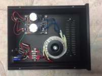
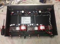
I'm trying to correct a lingering ground issue with my phono rig (Maplenoll Apollo, Lyra Lydian Beta and UFSP) and would appreciate your guidance. The audible 60 Hz hum is limited to my phono set-up only. As can be seen from the photos, my UFSP is in two enclosures, connected via a 5-wire umbilical.
On the power supply chassis, there is no connection between the RAW pcb's PE via and anything else. The toroid's shield and the chassis are connected to earth ground, as is a wire running through the umbilical to the UFSP chassis.
On the UFSP chassis, the earth ground from the power supply chassis connects to the UFSP chassis (both the chassis base and the front panel), the ground via on each UFSP pcb and the external ground stud on the rear panel. I added the ground connection to the front panel because it was isolated from the base; that connection isn't causing the problem.
The hum remains if I disconnect the four connections at the phono cartridge. The four clips are a little loose, but they aren't slipping off the cartridge's pins. On the other hand, the hum disappears if I disconnect the RCA cables from the turntables at the UFSP. Swapping RCA cables does not change that result.
I'm no engineer to be sure. Is the hum likely being caused by something other than my UFSP?
Many thanks,
Scott
Attachments
- Home
- Source & Line
- Analogue Source
- Simplistic NJFET RIAA