BTW do you play the piano?
I don't but two of my college age sons do, I orignally played trumpet. Lots of live music in our house - piano, guitar (acoustic/electric), bass, drums. We sometimes have jam sessions in the living room with some friends - when everyone moves out I'll have to get serious about piano, I really enjoy listening to it played.
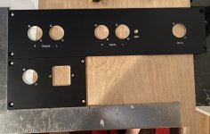
Chassis arrived today with custom back panels. Man, Gianluca at Modushop is amazing. I sent the CAD files late on Sunday expecting to hear back early in the week. I heard back in minutes, he fixed some issues from when I converted from FPD to DXF, and — 4 days later — they are machined, printed, and delivered in the US (all for more than reasonable prices).
PCX was sold out of all the caps I was interested in, so some CMR 2.2 and Miflex KPCU .1 uF are en route from HiFi Collective.
Fingers crossed for a successful finish to this build.
PCX was sold out of all the caps I was interested in, so some CMR 2.2 and Miflex KPCU .1 uF are en route from HiFi Collective.
Fingers crossed for a successful finish to this build.
Attachments
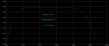
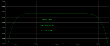
It's a modified Hagerman inverse RIAA.
I will have to simulate it for studying its details but it seems like it worked pretty good in practice.
I run the sims in combination with UFSP for your C2Y. That inverse RIAA worked very well for 1kHz square testing because together they keep necessary flatness up to 10kHz. UFSP does not cater for the extra "lost constant" or "mythical" 3.18uS pole (50kHz F4) included in the Hagerman so their combined response should be dropping faster in ultrasonic frequencies vs a classic Stanley P. Lipshitz inverse RIAA. Frankly lost constant sounds kinda pinched to me with records if included in the phono's RIAA network. So I avoided it in all phono versions. Other than it would make a 10kHz square look rounder than with UFSP's 100% compatible Lipshitz inverse, no other harm when using the Hagerman in testing.
Simulated -0.5dB Hag+UFSP shyness at 20kHz maybe reproducible on the bench or not, because exact HF can fall in the experimental error region of generator's cal response, scope's cal response, simulation's modeling precision, and passive networks parts tolerances.
Attachments
Salas & Co.:
Okay, I've gathered some data and would appreciate some guidance.
I managed to identify one source for the hum in my phono chain: I built an SG-4 turntable speed controller a few years ago and it was one of the culprits. Disconnecting the ground wire to the SG-4's output (which connects to the turntable motor) has eliminated that hum. The SG-4's earth ground and grounding within the SG-4 are otherwise intact.
Output from the UFSP's left channel is working fine. Output from the UFSP's right channel is hum only. I checked voltage drop across the following resistors:
R1: 0mv R, 0mv L
R2: 0mv R, 0mv L (S5 off)
R3: 48mv R, 48mv L (S6 on)
R4: 4.03v R, 4.06v L (TP readings)
R5: 0mv R, 0mv L
R7: 1.8mv R, 2.1mv L
R8: 157mv R, 158mv L
R10: 25.5v R, 25.56v L
R11: 12.4v R, 12.52v L
R12: 1.25v R, 1.10v L
R13: 0mv R, 0mv L (S9 off)
R14: 24.81v R, 24.93v L (S10 on)
R15: 0mv R, 0mv L (S11 off)
R16: 0mv R, 0mv L (S12 off)
R17: 0mv R, 0mv L
R18: 15.85v R, 15.95v L
R19: 0mv R, 0mv L (S7 off)
R20: 0mv R, 0mv L (S8 off)
R21: 1.40v R, 1.41v L
R22: 0.4mv R, 0.5mv L
I don't know how to interpret these readings, other than to note there is no meaningful disparity between the channels in any one instance. What would you suggest be checked next?
Many thanks,
Scott
What would you suggest be checked next?
Many thanks,
Scott
Voltage across Q6 & Q5 (drain to source each) on both channels
Salas:
I expect the problem is something incredibly simple but I am oblivious to it. The input and output RCAs have been tested, C3 and C4 check out just fine and I've reflowed all of the relevant solder points, all to no effect. I cannot find a point in the right channel that is inconsistent with the left channel.
I'll take a couple of days away from this problem and try again after the weekend, hopefully with refreshed eyes.
WTF?
Regards,
Scott
I expect the problem is something incredibly simple but I am oblivious to it.
Using same color signal wires and accidentally swapped hot for cold at some spot could be such a trap for instance

Salas the UFSP has unleashed a storm in my house, my wife is now requesting Sammy Hagar and Police on vinyl. In reading through the original build guide I noticed that C3 can be tuned depending on the output load and mentions .1uF for <50K and .047uF for higher impedances. I'm using a 100K load (outside terminals on a 100K potentiometer), the amp input is 270K and is on wiper to one of the outside terminals. I have .1uF in C3, should I change it?
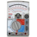
I remembered to try my cheap Pro'sKit MT-2017 analog meter yesterday, and you know what? Not only its Hfe measuring of TO-92 transistors was in the right zone but also watching DC fluctuations on its needle was more natural to monitor their swing. You don't get DMM accuracy, ok that's understood, but with just a glance you know if things are alright and how important a deflection is as a percentage. No decimal digits dancing party to watch.
Also no battery power is used up for voltage readings on a needle meter, so someone can hook it up and watch over something forever.
I believe I made this same point a while ago. With a DMM it is easy to get carried away chasing the last decimal place, when all we really need is a stable voltage in about the right place. Like you said, a glance tells you whether a change is large or small compared to the value you are measuring. It's more natural. I have an old cheap analog meter and ought to use it more, and I wish I had a good analog meter. When I worked in a stereo shop in the service department a lifetime ago, we had a very nice old VTVM I used for tuning up tape decks. I spent a lot of time watching that needle.
Salas the UFSP has unleashed a storm in my house, my wife is now requesting Sammy Hagar and Police on vinyl. In reading through the original build guide I noticed that C3 can be tuned depending on the output load and mentions .1uF for <50K and .047uF for higher impedances. I'm using a 100K load (outside terminals on a 100K potentiometer), the amp input is 270K and is on wiper to one of the outside terminals. I have .1uF in C3, should I change it?
Nice enjoyment!
Regarding C3 there was also "Use 100nF C3 only value when with MM" in the FSP guide. But FSP was the hardwired choose your single sensitivity configuration thing. To homogenize parts values in the UFSP, and only having to select DIP switch positions, C3 VLF slope coupling effect has been calculated with 0.1uF (100nF) only for all sensitivity options.
In case of a high impedance follow up stage (99% likely its tube gear) you could save money and size on C4 instead. Using a higher regarded cap for less $. With 100k load a 0.47uF C4 should have the same VLF shaping effect as a 2.2uF on 20k load.
I believe I made this same point a while ago. With a DMM it is easy to get carried away chasing the last decimal place, when all we really need is a stable voltage in about the right place. Like you said, a glance tells you whether a change is large or small compared to the value you are measuring. It's more natural. I have an old cheap analog meter and ought to use it more, and I wish I had a good analog meter. When I worked in a stereo shop in the service department a lifetime ago, we had a very nice old VTVM I used for tuning up tape decks. I spent a lot of time watching that needle.
Attachments
- Home
- Source & Line
- Analogue Source
- Simplistic NJFET RIAA