@jphabc54
Try with the phono's VR first with major adjustments for nearest possible to T.P goal, then tweak the shunt's VR for helping with changing the rail from 34V. For your now 32.3V rail the other voltage drops compute. About 1U chassis, difficult to fit. What If your C3 was smaller like an Auricap or something?
Try with the phono's VR first with major adjustments for nearest possible to T.P goal, then tweak the shunt's VR for helping with changing the rail from 34V. For your now 32.3V rail the other voltage drops compute. About 1U chassis, difficult to fit. What If your C3 was smaller like an Auricap or something?
@pfarell
The LED array values are somewhat lower. In the previous strong generic reds in the prototype were difficult to chance upon again. Most builders did not reach my VF figures with just reds and fastidious ones mixed a green or something. In the UFSP the 4V T.P and the rest of voltage drops were checked with Kingbright red flats. Those are much more VF consistent than generic reds.
I am a bit reluctant to give a VF total absolute value though because a. It isn't a make or break figure b. Q7 CCS samples may differ for IDSS and that affects VF total from build to build. So to avoid creating non productive accuracy stress to the builders in a sector that still works for T.P with some tolerance anyway.
Thanks Salas. So use what Tea sent and then act/adjust accordingly? In the previous build I bought a ton of reds, and then realized that Tea had included quite perfected sets of yellow, green, and red flats to achieve the voltages in the guide...so mine anyway on the last build were very exact.
@jphabc54
Try with the phono's VR first with major adjustments for nearest possible to T.P goal, then tweak the shunt's VR for helping with changing the rail from 34V. For your now 32.3V rail the other voltage drops compute. About 1U chassis, difficult to fit. What If your C3 was smaller like an Auricap or something?
Thanks Salas -- 2U will be fine -- still doing some final planning before I make a final decision though. I don't want to limit my options for changes down the road, so 1U might be a bridge too far.
Highest I could get the rail voltage is 32.5v -- VR1 on the main board switches off at this point. At 34v rails, I can only get TP down to about 4.5v before VR1 on the main board switches off.
@pfarrell
Yes use what he sent. In the previous the many LEDS sorting to chase that VF thing happened and I think it should not happen again. Experience from builds feedback told me its not so crucial to follow the prototype exactly in those details. Only do a check for DC voltage drop across Q1 or Q2 drain to source. Between channels also. And let me know those VDS results.
Yes use what he sent. In the previous the many LEDS sorting to chase that VF thing happened and I think it should not happen again. Experience from builds feedback told me its not so crucial to follow the prototype exactly in those details. Only do a check for DC voltage drop across Q1 or Q2 drain to source. Between channels also. And let me know those VDS results.
Thanks Salas -- 2U will be fine -- still doing some final planning before I make a final decision though. I don't want to limit my options for changes down the road, so 1U might be a bridge too far.
Highest I could get the rail voltage is 32.5v -- VR1 on the main board switches off at this point. At 34v rails, I can only get TP down to about 4.5v before VR1 on the main board switches off.
2U is wiser choice in the long run as you say.
What IDSS your Q1 Q2 have and maybe you can afford different rail voltage for say LMC mode switches setting?
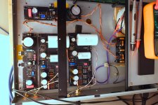
Sorry to interrupt the flow of new stuff but my latest update on the old FSP is that it is being used in anger now. Oh wow, what a lovely thing, even with the std 47k loading it knocked my socks off and all the fav records got a run out. The overall picture is huge and very well balanced. I am having a play with the loading with 100r a bit muffled. 220r might be the sweet spot but I am happy with 470r currently. More messing to be done. Overall impression is of weight and control a world apart from the Naim phono cards I was using before.
Pic of the final build and in system. BTW, no prizes for spotting the small error in wiring, oops.


Pic of the final build and in system. BTW, no prizes for spotting the small error in wiring, oops.
P.S. We already know that we succeeded to a not worse UFSP despite the extra facilities and there are indications it might be better than the classic FSP even, mainly due to its shunt reg section update, but we wait for wider users feedback to sunk in before concluding on how close FSP is and if it still holds some areas of superiority.
In any case its no slouch. Enjoy.")
In any case its no slouch. Enjoy.
2U is wiser choice in the long run as you say.
What IDSS your Q1 Q2 have and maybe you can afford different rail voltage for say LMC mode switches setting?
Thanks Salas -- Q1 is 11.18ma and Q2 is 11.21ma. I switched to 56dB gain and there I was able to dial in 4.00v no problem with 34v rails. I was not able to source R13 yet, so can't observe 63dB behavior.
Initial use will be with MM and HOMC carts, so it would be with the lower rails in this case, but I'm building the UFSP mainly with the aim to get a LOMC in the system in the near future.
In FSP builds it was many times the case they ended up with 32-33V rails especially when building it for HMC or MM. But there was this in the PDF instructions gain section: "Choose Q1 between channels from a 10.5-12.5mA range at 5% IDSS pair tolerance" (HMC MM). In UFSP there is more voltage space I left in case of depleted lower IDSS K369 choices in the future. To can still be trimmed for T.P in low gain modes even with say 15mA IDSS K369.
So now that I know your K369 IDSS I also know your rail is as it should for high output MC mode. It computes perfectly.
Nice. Keep us posted. I know how good the Valve Itch you already got is to tube lovers, I actually have a couple of friends that stubbornly wouldn't replace it for my JFET designs, or anything else for that matter, but my assessment to them was at least have both.
I find the Valve Itch maybe more fun at medium volumes with character carts playing the blues etc. but when the going gets tough with program complexity and loudness on more neutral and dynamic audio system setups the FSP/UFSP are the more open natural players. IMHO of course.
I find the Valve Itch maybe more fun at medium volumes with character carts playing the blues etc. but when the going gets tough with program complexity and loudness on more neutral and dynamic audio system setups the FSP/UFSP are the more open natural players. IMHO of course.
I can’t imagine anything bettering the Valve Itch, but I simply couldn’t resist the opportunity to build a UFSP. I can’t wait to compare them side by side, and it will be nice that the UFSP will be ready to support low output out of the box (which will of course put me in the market for a SUT for the itch)...it..never..ends...
I finished the other channel on Saturday and spent most of Sunday listening --including a little Led Zeppelin retrospective following Salas' post...
The discussion on the choice of C2Y came just at the right time! Teabag measured C2 at 14.93nF for me, and tonight I added 220pF from the helpful little bag of C2Ys he's included in the kit -- wow, that gave just the right last little edge towards clarity and transparency -- it's pretty amazing, am very happy.
I'm surprised how little heat the MOSFETs are producing. I expected something more like the DCB1 Mez, but no, there's almost nothing. I'm using a re-purposed chassis, and basically put the MOSFETs where I could find a tapped M3 hole -- I didn't even screw down M1 which, surprising to me, even then isn't getting hot. This way, I didn't have to drill or tap any holes at all!! yes, I'm lazy -- until I'll clean everything up later.
I'll listen for a few more days and try a few things. I don't have a grounding scheme yet and also will partition off the power supply -- but it is already pretty quiet.
One thing I'm trying to understand is how the bias is wandering around, starting at 5.3V when switching on and then random walk around 4V +- 0.3V, basically. I'm trying to understand more of the design, started to read from post 1, but if you guys can point me to maybe a discussion or walkthrough or circuit description, I'll be very interested to read up!
Attachments
Hi, nicely done up to now. 
There's a circuit description link in post#1 named how it works. Q1 Q2 bias goes through warm up time of thermal stabilization when starting.
M1 is lukewarm when RawDC Vin isn't too high. VDS M1 is Vin-Vout. Dissipation Watt M1 is VDS*CCS (100mA for R1 5.6R standard). If you hot-rod CCS mA a bit (145 mA with R1 3.9R) the diss W goes quickly up. For M1 and mainly M2. M2 is shunt to the load burning excess mA at 34V level. Each channel with both Q1 Q2 engaged is about a 36mA load.
You may confirm your shunt regs correct mA settings by measuring the voltage drops across their R1 and then dividing it by R1's value in Ohm.
Salas and Tea: Hats off to making incredible changes to the "build-ability" of this fantastic phono pre. Been having a little back and forth with Tea and it's clear to me now that the Ultra version is WAY more noob friendly than the previous build (Safe to say the FSP was pretty advanced actually). This I love since it could open up a lot more makers for this project—granted we are all somewhat rarified in this teeny world of DIY PLUS turntables and then some prerequisite OCD? Ha. As a much newer builder I most certainly needed help on the FSP build—and it required "locking" in some specifics with regards to carts etc as you know. Obviously I'll report back when Ultra is up and running...
- Home
- Source & Line
- Analogue Source
- Simplistic NJFET RIAA