I just finished my build and switched it on. One channel I get all the LED's and the other channel the 4 on the side never come on. I am overwhelmed where to start, are there common issues that would cause this?
Also, my Raw PSU is putting out about 27V DC. Is that enough? I saw in the biasing that it is looking for 35V
Also, my Raw PSU is putting out about 27V DC. Is that enough? I saw in the biasing that it is looking for 35V
Get a 32V+32V toroidal (four wire). One secondary to each RAW DC board's input.
perfect, thank you! I will get that installed and then see what the board LED's are doing.
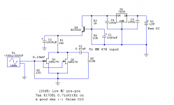
Salas: for the MC step up in the original Nfet phono do I need to change any resistor values (R1?) when using 8.2mA jfets?
I built the MC step up. Sounds very, very good. But it's very sensitive to placement. It must be a meter away from my big class A amp for best results. But it is not in a metal box yet.
Running off batteries for now. Works as advertised.
Anybody compared this against a transformer SUT?
Good screening for sensitive circuits in traditional diy fashion comes with dead bug style construction on a raw board's copper back housed in a tin can.
I prefer direct high gain input where hum and buzz problems can be solved without a step up transformer.
I think some of the problem with this is my turntable, a Rega. It has no separate ground wire and I was using the step up as dual mono (2 battery packs). The only way it was quiet was if I tied the Left and Right RCA grounds together.
Also, I experienced a strange loud BUZZ when I my hand was about one inch away from the record on the platter...Not touching, just hand above platter.
Good screening for sensitive circuits in traditional diy fashion comes with dead bug style construction on a raw board's copper back housed in a tin can.
I prefer direct high gain input where hum and buzz problems can be solved without a step up transformer.
Hello Salas,
I was contemplating the same these days ; and started by acquiring tined steel boxes(1/chanel) composed by top and bottom plate and moving both gain stages in there. The main drawback is the ridiculously large inter-stage 100n russian mica capacitor that is at this point an antenna for 50Hz hum.
How one solves that ? a Polypropylene capacitor is linear enough at that point (anyone compared different builds with different interstages? R-Cruz maybe ?)
My status: In process of finding 100n mica's that are comparable in size to a jfet so all the stages except buffer to fit in a 3cm/5cm shielded enclosure(but it seems impossible).
Last edited:
If the big Soviet era cap has a metal shell see if you can scratch it somewhere and put solder on to run a wire from it to a ground point.
is aluminium
and funny you mentioned it; i managed to create a soldering point using a 22000uF @35V and some thin copper wire discharging it repeatedly in a pad like area
")
It seemed too much of a improvisation to mention or use it.
But after a couple of hour seeking an alternative; incorporating it seems a better option. But i will build a steel enclosure for it ; aluminium is worth nothing when it comes to shielding.
Cheers.
P.S So no comparison to just use a different capacitor or none ?
Aluminium is difficult to solder on but maybe you can devise a wire retaining band.
There are many good alternative modern capacitors. None is not an option, it's a coupling position and it's necessary.
About soldering on aluminium; thats the trick; just discharge a fairly large capacitor using a thin copper wire on its surface ; and after a dozen discharges ; a copper pad will be strong enough to magically solder where none has soldered before
Ok ; i will just try some pp capacitors then.
When i said none i was thinking to simply a strap but i have little knowledge in the stability implications.
We see about that next. Maybe one LED is in reverse, or somewhere around them a voltage isn't right, something. If one channel is alright you can compare the bad one's voltages at points.
ok! so I have a new transformer in there and a 20R 5W in RD Link and I am now getting 51V DC out from the Raw PSU. At DC IN on the board, it is 44.8V. I was able to get the voltage to 35V between GND and RAIL+ for both channels.
The channel with the working LED's I was able to bias TP1-TP2 correctly to read 3V. The channel with the non-working LED's reads TP1-TP2 of 35.06V same as GND to RAIL+ of 35.06V.
I found that one of the LED's in the set of dark four was installed backwards. I flipped it around but they still didn't work. I am concerned i may have damaged the one LED when I was taking it out. It is one of the flat types from Teabag's GB and it now has a small crack on one side that half way across. I am concerned that if I need to replace it, that it won't match the other 3 in the set. What would you recommend?
Is there anything else I should be checking? Thanks so much for the help!
- Home
- Source & Line
- Analogue Source
- Simplistic NJFET RIAA