Okay. My apologies, I thought that my report of 25.25V at V+ on both boards was what you had been looking for.
That's great, and thanks again for advising me. I will order up those parts post-haste.
While I'm ordering, should I be looking at anything off of the power supply? What should I be getting at V+ to ground? I thought I was alright with my transformer putting out 18V AC for rectification. Amperage at the input to the boards is 39.5mA at board 1 and 36.6mA at board 2, do I need less resistance in the power board, or more voltage? Where should I look into getting more to the board?
Last edited:
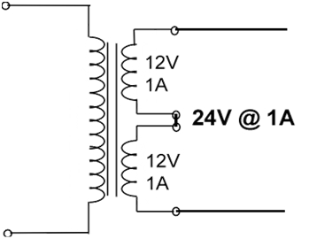
There is the rectification and main reservoir capacitors dual mono PSU that accepts the transformers AC. That one comes before and externally to the boards. Needs two transformers of 18+18V secondaries wired in series in each to make two 36V AC transformers and convert that to raw filtered DC lines that will be delivered to the boards.
If you kept them transformers at 18V level then its absolutely normal that nothing would initially work correctly. That is why I was repeatedly asking you the DC input level to the main boards. Should be nearing 50V DC.
Make that part right first and only then we can estimate any other possible defects downstream.
P.S.
Some 33V dual secondary (four wires) transformer will also do if you don't want to go dual mono magnetic cores.
Each 33V secondary to each raw PSU's AC input will make about 45V DC output lines, one for each main board's DC input connector.
45V DC is also high enough for the shunt regulators use and it even creates less heat on Q1x's sink.
P.S.
Some 33V dual secondary (four wires) transformer will also do if you don't want to go dual mono magnetic cores.
Each 33V secondary to each raw PSU's AC input will make about 45V DC output lines, one for each main board's DC input connector.
45V DC is also high enough for the shunt regulators use and it even creates less heat on Q1x's sink.
I’m eagerly awaiting another dual 18v so I’ll have one to run in series to either side, feeding each rectifying circuit 36vac so each shunt circuit should see close to 50vdc, right? I went ahead and replaced all of the questionable components already. I should be able to check again on Friday. Thanks again, Salas.
Here is an example of a decent transformer to use:
AS-1236 - 100VA 36V Transformer - AnTek Products Corp
Quite affordable, doesn't hum, has an electrostatic screen between primary/secondary, and will give you your raw AC for both chanels.
As Salas stated you should have roughly 50Vdc after the rectifier and caps on your raw PSU going to the Folded Phono boards. You stated that you measured 30Vdc. almost 20 volts too low!
If you look in the build guide PDF, you will see that the Rail+ to ground measurement should be 35-36Vdc. You are 10 volts too low. The shunts aren't getting enough voltage to do their job.
If your current transformer has dual 18V secondaries (18-0, 18-0) you could wire the secondaries in series to get 36Vac and this would get you going to test the rest of the circuit. I imagine you could even run both channels off the one single +50Vdc raw supply for now. It won't be ideal, but should work just fine, and you will know if it actually makes sound or not.
Welllll, it’s not exactly pretty, here in Tennessee, Salas. My input voltage is spot on 50.1V. Both channels right on. I went to check the rail voltage and it was an anemic 25v, but VR2 was set very low . I cranked it up, but only ever reached 31.5V on Board 1 and 32.9 on Board 2. Then the even more puzzling reading occurred. After dumbing Board 2 down to 1’s max level, my TP1-TP2 read B1=6 and B2=7.5!? I must admit I’m feeling a might discouraged. The only real observation I can contribute is that B1’s Q1X is as hot as Q6X. Not sure if that helps.
Don't be disappointed, because things finally started heading in the right direction.
Measure the voltage drops between R1x legs in each board first so we see if they pull expected CCS current levels.
Reset each VR1 to about half turns if they had been previously manipulated.
Add 1.5k in series with each R3x so the rail outputs can reach even higher with VR2x.
Or replace R3x with 11k Vishay MBA02040C1102FRP00 (Mouser no: 594-5063JD11K00FT).
I’m full of new developments and revelations. I had R3X at 6.2K for some reason and R6X is at 27. So when I figured that out and went to replace at 9.1, I could only locate one. So I went ahead and swapped out Board one’s R3X for the 9, and now the rail won’t dip down to 34V and TP1-2 is only going up to 2.2V. So, if I was a betting man, I’d think I should be aiming for an 8R5K or some such like it. Should I also procure a 22R for R6X? For some reason my choices were 27R or 33R. I have a feeling that to hit the 3.6V target I’m going to have to dip below the 34V mark at the rail as it stands now. Thanks
IR drop at R1X on Both boards is 1.54V
IR drop at R1X on Both boards is 1.54V
Last edited:
R6x's value isn't a consideration for the setting of the regs. Its about how many mA run through Q2x and the three LEDS it drives. To keep that JFET not too cold not too hot. As it is exposed to high voltage drop and samples IDSS differs we use R6x to control Q2x's dissipation for long term reliability. Measure how many mV are dropped across each R6x and I will let you know if to change anything.
If you piggyback a 100k resistor on the 9.1k (R3x) they make 8.34k. Try that. VR1 adjustment could also help reach your T.P. goal when near.
IR drop 1.54V on both R1x is an excellent reading because we are aiming at 100mA in this design. The Q1x MOSFET and the three LEDS have Vgs & Vf sample tolerances so when ending up with +/- 10% current setting results is good. 1.54V across 15 Ohm R1x means 102mA CCS for both regs. Spot on and matched between channels in your case.
I replaced R3X with an 8R5K set the variable resisters to half and gave it power. Had to roll up just a little bit to get to 35v rail on both channels. TP1-TP2 both came in at 2.4ish, further downward adjustments got both channels to 3.6 easily and, well, easily. I’m right now watching it sit for a half hour to give some final tweaks to hit 3.6 for good. Out of curiosity I checked DC at the outputs, and both sides were dead on 3.4mV, so I’m thinking that that’s a good sign. After It idles for a while and gets a final biasing, is it time to hook up?! Thank you for the coaching, Hoss. It’s pretty awesome that you not only designed this amp, but you’re willing to talk amateurs like me through the finer points. It takes patience and a good bit of kindness, and you have my respect. I’ll let you know how it sounds if that’s where we’re at...
Last edited:
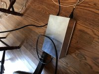
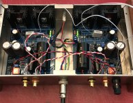
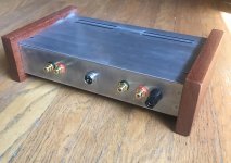
Yessir there may still be mods to do. I wouldn’t have thought there would be buzz with only rectified DC present in the amp unit. Well, at least I’ll know where to start if I get some. As far as the sinks, not sure what brand they are, but thanks, I suppose they are pretty nice. I just noticed the picture cut out all my hard work I did to gussy up my chassis. Here’s one more pick, just for the sake of vanity.
Attachments
If it's set for high gain MC mode there are always opportunities to pick some buzz from AC magnetic fields in the larger area. Other equipment's trafos, mains cables, RFI, etc. It depends, not all installations face the same external factors. Keep boxes with trafos well away if able. There are ground loop opportunities also, matter of grounding scheme and how's compatible to the rest of the system's ground.
It’s taken a few months, and I’ve traded out some parts, but this amp makes quality music. First off, no noise at all until I’m a notch past ridiculous, unlistenable levels; I thought I had pretty good components, now I know what the noisy link was. Right away the stereo imaging is wider and especially deeper, and there’s a ton of detail. I’m keeping in mind that it’s only in it’s first hour of operation, and there’s a whole device worth of components that have to burn in for fifty or so hours, but at this starting point it sounds better than the Parasound Z-Phono I was using. Started with the Flaming Lips, Transmissions... and that was a lot to throw at a new amp, it was a might bit muddy, but that should clear up real good soon. Now it’s Gillian and David’s album The Harrow And The Harvest, and it’s clear that we have a winner. If you can convey the tone of the clawhammer banjo, something or two is working in favor.
I’d like to thank my endlessly suffering wife who’s been without use of the dining room table as it’s been under a pile of resisters, transistors and capacitors, not to mention the dust broom after dust broom of trimmed leads. Hey Sweetheart, I’ve only got one more phono stage and a power amp to modify and we can eat at the table again!
And Salas, who walked me through the valley of the shadow. Thanks. You designed a freakin killer amp.
Last edited:
Congrats, you are welcome. Quiet enough as well. What is your TT & cart?
Regarding finer details / tuning (after it clocks in enough replay hours) input load choice plays a tonal role and C2Y is a place to brighten it or dim it (less C2Y value makes for brighter and vice versa). Coupling caps are the costly preference stuff of course, so if ever itching for deeper tuning, better not play with them before exploring the arm-cart geometry and the other mentioned easier options.
But replace with something better in MKP that leg extended grey 4u7 MKT at the PSUs when you get a chance. What caps are your C3s?
As for trimmed leads abound, say something poetic, like they are the fallen crumbs necessary to remind a feast of creative inspiration.
Hey, all right, quiet? Yesssss. I’m using a Denon DL-103 on a Kenwood KP-990, and I come out of the Salas Folded into a modified Xiang Shen DAC 01A. Then I kinda bounce between a Schitt Vali 2 and using the WHAMMY headphone amp I built into either a NAD 2600 or the Acurus A-150 that I just today finished re-capping (tossed the Wimas and changed out the power caps and switched the electrolytic for Nichicons) so we’ll see how it sounds tomorrow, for speakers, right now Polk SDA 1Bs but usually Legend Audio LEG-7000s. And when the table’s spinning and there’s no signal there is absolutely no noise coming out of the speakers until they’re at 3 O’ Clock. It’s spooky.
My C3 caps are Robert Hovland Super Caps, I chose them because in a review they were called “honest” and I liked that because I’m striving for detailed neutrality.
Out of curiosity, what does the C2X cap do sonically? I don’t just want to throw the newest, most expensive cap of the hour at it. What is the function? What characteristics or specs should I be looking for?
Thanks again for your time, and answering my questions .
C2X is terminating the PSU. Connects to the R5x in series to do that without ringing. Its essentially the PSU's output capacitor. So it has some influence. You could try a Wima MKP10. MCAP EVO OIL 4u7 also fits and its not too expensive. That one was best recommended for the specific position by some builders in the past.
- Home
- Source & Line
- Analogue Source
- Simplistic NJFET RIAA