could such a device produce an inverse RIAA sweep?
Should be no problem, an arb function generator usually reads out a large data buffer at a constant clock rate. The features say that a 2M buffer is standard and that would be 40sec at 48k sampling. Any program like Octave or Python could easily generate the data file.
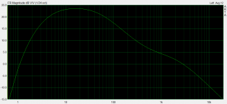
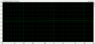
Scott, there's another practical way too, I used a RIAA playback curve in ARTA as FR comp. The software works by reversing for it. I run a test on breadboard with a times 10 Jensen SUT, an AD8429 as first stage, an OPA2134 as second stage and servo, passive RIAA in the middle. 1% RIAA parts were used with no selection. 62dB total gain. FFT grass stays at -102dBV 20Hz. Given the opportunity I implemented the mild subsonic filter in the servo, so no direct capacitor coupling anywhere. And here is how it can be verified against frequency: First pic is the actual transfer, second picture is the compensation to flat against the time constants derived 20Hz-20kHz cal file.
Attachments
Scott, there's another practical way too, I used a RIAA playback curve in ARTA as FR comp.
Looks good too!
") Another way to skin this cat.
Another way to skin this cat.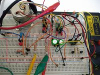
Which gain level to build for a .5mV cartridge?
I have a .5mV output Ortofon Quintet Blue cartridge, and am wondering which gain level to build for it. The build guide says that "for .5mV+ cartridge and enough amplification in your control preamp ... build for 56-57 dB". I am using a passive preamp and my power amp has 30 dB of gain.
If possible, I would like to do the 62-63 dB gain configuration to allow the use of lower output cartridges in the future, but I am concerned that it may not work with the .5mV cartridge I have now.
Any input would be greatly appreciated.
I’m of the opinion that a MC cartridge should be attached to a step-up transformer. I’d build the simplistic for ~40db gain like for a MM, which will happily interface with a transformer.
Others may recommend a different approach, but I’ve done this configuration with excellent results.
Others may recommend a different approach, but I’ve done this configuration with excellent results.
Look, 0.5mV with 61-62dB as usually achieved by 2XK369 in this circuit will bring double the nominal output level from the phono (i.e. hitting near 600mV for 5cm/sec) so it will squeeze the overload margin by 6dB and push THD. It has been done before and it can sound more vigorous in low total system's voltage gain with inefficient speakers situations but its not that optimum. For 57dB one K369 is left empty and you could use female pin sockets for it and the rest of the configurable components so you can easily reconfigure without desoldering and decide.
Configuring for MM and using a SUT makes for an MM/MC inputs ready phono and its surely more versatile for someone who has both types of cartridges or more than one turntables.
Configuring for MM and using a SUT makes for an MM/MC inputs ready phono and its surely more versatile for someone who has both types of cartridges or more than one turntables.
Salas and 6L6 thanks for helping with my question (and so many others as well). The idea of using a step up transformer is interesting. Would 40dB on the phono preamp and 20dB from the SUT cause the same overload margin and THD problems mentioned in Salas' post for the 61-62 dB gain preamp configuration?
Salas SSLV1.3 Ultra-BIB
When having a look at other power supply modules provided by Salas (and group buys by Tea-Bag), I saw the Salas SSLV1.3 Ultra-BIB and wondered if this could be used with the Simplistic NJFET RIAA ? If so, how would one go about adapting it to the Simplistic.
Cheers
Frank M
When having a look at other power supply modules provided by Salas (and group buys by Tea-Bag), I saw the Salas SSLV1.3 Ultra-BIB and wondered if this could be used with the Simplistic NJFET RIAA ? If so, how would one go about adapting it to the Simplistic.
Cheers
Frank M
You could skip populating all the regulator parts on the FSP board (as listed under "Regulator BOM" in the guide) and feed at the RAIL+ GND points from SSLV1.3's output instead. Those points are located near VR1 and Q5. An Italian member with doubled up balanced mode FSP already made the move and recommended it as a significant sound quality upgrade for this phono.
"I've upgrated the FSP with Ultrabib 1.3 and now it's another story.
Everything is much better, clarity, transparence, dinamic, soundstage and energy.
My FSP is balanced, yes I've two printed circuit everyone managing the + and - of the
cartridge output. The gain is 56dB with only one K369.
I desoldered the components of the original volt regs and piggybacked the new ones.
R1 is 5.6R for about 110mA of ccs current.
The sinks of M2 are 7C°/W and the temperature is not hot.
Thank you again Nick"
Orelli (thread: "Salas SSLV1.3 UltraBiB shunt regulator" post#833)
Two positive i.e. one +/0 Vout for each channel substituting the original onboard ones (dual mono). In the balanced example there are four same circuits serving two opposite signal phases per left and right channel. Thus mr. Orelli constructed four FSP sections (found in two unbroken boards) and four positive Ultrabibs.
Hello Salas, Merry Christmas wishes, I have your sslv1.1 cards that want to be used, and you think it's time to do it, what schematic do you recommend to build to use them? Still happy Christmas to all.
Tiziano
Last edited:
Hello, thanks. We were talking SSLV1.3 UltraBiB. The FSP has 1.1 class PSUs on-board already.
I had understood that it was version 1.3, but I did not want to buy the pcb and I just wanted to build the phono with pcb PP and use my power pcb
When you want to build it on matrix card point to point and use SSLV1.1 to power it, go to post#1 here and go to link #3 for FSP guide with schematic. Do the phono schematic from there, then go to SSLV1.1 builds & fairy tales that has everything about 1.1 BiB and learn how to build it for 35V range
LED Matching Question
When measuring the Vf of the LED's, is there a target current level that the measurement is to be taken at? Based on the build guide suggesting a 9V battery and a 1.5k resistor be used, and that a quartet has a 7.75v I am calculating that the target current level would be ~4.7mA
(9V-7.75V/4)/1500ohm=4.7mA
Am I looking at this the right way?
Thanks!
Look at it this way instead: There is a jfet that you will use as a current source to pull current through the LED's. Take that FET, the actual one you will use in the circuit, put it in a socket, arrange a voltage source similar to what it will see in the circuit (I would suggest two 9V batteries in series), and use that current source to measure your LEDs, either individually or as a group. Do it again with the FET you will use in the other board, etc.
In other words, the current is set by the Idss of the FET, which varies slightly with Vds. You will select LEDs to give the target voltage with that current.
In other words, the current is set by the Idss of the FET, which varies slightly with Vds. You will select LEDs to give the target voltage with that current.
- Home
- Source & Line
- Analogue Source
- Simplistic NJFET RIAA