Better reserved for differential input stages
True, I do believe I have more K147BL then J72BL, I could go that route, but it would be interesting to run the K146V at 20-24ma and see the effect.
Mad
Those are the canned ones , right ? with a small red dot for pin out orientation ?
I have put them in parallel once to serve as MC headamp battery powered , works okay !
I thought Borbely have used these in one of his hybride phono amp designs as well .
Happy Spinning ,
Paul
I have put them in parallel once to serve as MC headamp battery powered , works okay !
I thought Borbely have used these in one of his hybride phono amp designs as well .
Happy Spinning ,
Paul
Hi Salas,
Just got the boards and kits from TB - awesome work as usual. And I’ve just submitted my mouser order for most bits.
Question - should I use an audio specific capacitor for C4? I’ve ordered the following - will these work well from an accuracy/Engineering perspective?
75-MKP1839522164
MFG Part No: MKP1839522164
Vishay / Roederstein 2.2uF 160volts 5%
80-C4GAFUC4220AA0J
MFG Part No: C4GAFUC4220AA0J
KEMET 400volts 2.2uF 5% / Film Capacitors
647-QAK2E225KTP
MFG Part No: QAK2E225KTP
Nichicon 2.2uF 250 Volts 10% / Film Capacitors
Thanks Salas.
Hello, from those three the Nichicon is MKT so skip it, between the two MKP the Kemet 400V looks preferable at 2.2uF for dissipation factor than the Vishay. If you will ever want to subjectively compare an "audio" type MKP the rather moderately priced (as luxury components pricing goes) Mundorf plain vanilla Supreme (SUP8-2,20) should be enough for curiosity's shake vs industrial MKP.
Having same Vftotal quartets and triplets is priority to absolute value because it keeps the cascode voltage bias the same between channels. Don't worry much for guide's refVftot when in the close neighborhood if you can't reach it or just mix a green LED but its not the best thing to do aesthetically.
Test for 4-5mA current. Itest=(Vtest-Vftot)/R
Use 15V-20V. You can also use the K117 Q7 prepared for the board in IDSS mode instead of a resistor to feed them current. That will be even closer to the specific in circuit conditions. If without lab PSU stack 2x 9V batteries up.
Hi Salas - me again - I’m thinking my greatest challenge with this build will be LED matching (since TB has done most of the hard work with the other components). I tried measuring Vf of single LEDs using resistor circuit (1.x kohm resistors), but my voltage readings jump around significantly depending on slightest movement of LED in breadboard and remeasuring the same LED would be different each time!

Can I measure a single LED using K117 in series instead of a resistor with 9V battery? So the series circuit would just be 9V battery > K117 (G-S shorted) > LED. Just concerned if I would damage anything ><
I think testing 3 to 4 LED strings would be harder to make a matched set. I’d rather building up sets from single LED measured values.
Thanks Salas
Hi Salas - me again - I’m thinking my greatest challenge with this build will be LED matching (since TB has done most of the hard work with the other components). I tried measuring Vf of single LEDs using resistor circuit (1.x kohm resistors), but my voltage readings jump around significantly depending on slightest movement of LED in breadboard and remeasuring the same LED would be different each time!
Can I measure a single LED using K117 in series instead of a resistor with 9V battery? So the series circuit would just be 9V battery > K117 (G-S shorted) > LED. Just concerned if I would damage anything ><
I think testing 3 to 4 LED strings would be harder to make a matched set. I’d rather building up sets from single LED measured values.
Thanks Salas
With the minikit, measuring them is not needed. The Kingbrights in minikit are very tight and consistent for their vf
Should go like this
D1-D4x D1x any red, D2x-D4x two yellow one green. (5.83)
D1-D4 - RIAA section, two yellow, two green (7.80v)
I’m looking for one of Salas FSP. If someone has spare boards, completed unit or what have you feel free to contact me.
I have the board and some parts available.
It is all listed in first post of following thread.
http://www.diyaudio.com/forums/grou...-folded-simplistic-phono-pcb.html#post3615620
Private message me if you are interested. I do not have/do any built up units.
Hello, from those three the Nichicon is MKT so skip it, between the two MKP the Kemet 400V looks preferable at 2.2uF for dissipation factor than the Vishay. If you will ever want to subjectively compare an "audio" type MKP the rather moderately priced (as luxury components pricing goes) Mundorf plain vanilla Supreme (SUP8-2,20) should be enough for curiosity's shake vs industrial MKP.
I went and got a pair of Supremes as you suggested! Board stuffing complete, waiting for transformers to finish the PSU then testing time
I’m planning on building the 40DB version - and the guide state “Choose Q1 between channels from a 10.5-12.5mA range at 5% IDSS pair tolerance.“
The 369’s I have are up around ~15 mA - should I adjust any resistors from the guide to suit?
Thanks
Its either change the 5.6K 1W R13 to 5K (10K//10K 0.5W), or higher than average Rail+ will be likely needed to achieve 3.6V TP1-TP2, maybe circa 37.5V. The second option gives more voltage headroom to the following gain stages which is a good thing, but you may also need higher value R3x in the shunt PSU section if your VR1 max setting does not produce high enough Rail+
Good luck and let us know. By the way what you got for C3?
I got an MKP1837 100nf. I think this was recommended in the thread.
Its either change the 5.6K 1W R13 to 5K (10K//10K 0.5W), or higher than average Rail+ will be likely needed to achieve 3.6V TP1-TP2, maybe circa 37.5V. The second option gives more voltage headroom to the following gain stages which is a good thing, but you may also need higher value R3x in the shunt PSU section if your VR1 max setting does not produce high enough Rail+
Thanks Salas I’ll try option 2 with the increased voltage. Thanks.
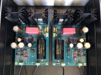
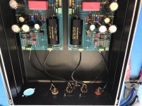
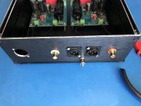
Progress so far - phono boards cased ready for testing. XLR sockets just because my downstream gear is all balanced and I am too lazy to make a custom cable
No case for the PSU yet, size it up after I get the trannies.
No case for the PSU yet, size it up after I get the trannies.
Attachments
- Home
- Source & Line
- Analogue Source
- Simplistic NJFET RIAA