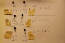
The SK170s. Usable deviations? Measured with 9 V and 100R. Shall I organise in any special way?
You could use 8.44 & 8.56 for Q4s. They are the closest ones.
8,27 and 8,72 on Q6 then. They were tighter on Mikes measures (texted on tape and bags), but not when I control measure. If Mike is there, what method did you use?
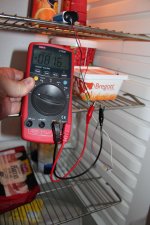
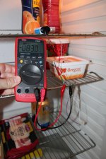
I measure at 10V with HP power supply, through a Fluke 87V.
I make sure that room temp is 72 degrees (heat pump can do well here)
For the 2sk170's I don't measure for too long, under 5 seconds.
@ Mike
Maybe 0.047uF Jupiter would be also enough.
I would concur in my system it might have been more ideal in practice, but I'd rather have a little more low end than not enough. At some point I would like to do drive rack like VGeorge and use microphone to help adjust bass. Not in the cards today, power outage killed HDMI TV Monitor - so no USB digital sound or Playstation for the kid. Getting that fixed or replaced is priority.

I measure at 10V with HP power supply, through a Fluke 87V.
I make sure that room temp is 72 degrees (heat pump can do well here)
For the 2sk170's I don't measure for too long, under 5 seconds.
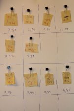
Strange. My values follow yours (Q4,5,6) but have much larger deviations between the pairs. I do have 28 degrees C inside, som 82 F but I wonder if this can do it.
Remeasured once again with 9 V 100R and got about the same. Changed the resistor to 10R and writed them values in (x).
Well, maybe my Uni-T UT60E is bugging me and the values arent far out anyway.
PS. In my measures Idss rises some 100 microA the first 30-60 seconds.
Attachments
Last edited:
Polaris Electronics.
Ok, I'll arrange it like this:
Ch1 Q4 8,44 Q5 7,14, Q6 8,27
Ch2 Q4 8,56 Q5 7,71, Q6 8,72
tomorrow
I also think this is how I will arrange R1+ Rx1-4
47 47 18 18 6,8
This gives me those combinations:
47//47 = 23,5
47//18 = 13,5
47//47//18 = 10,2
47//18//18 = 7,55
47//6,8 = 5,94
47//47//18//6,8 = 4,08
47//18//18//6,8 = 3,58
47//47//18//18//6,8 = 3,33
And 47 alone ofc. Thoughts about that?
Last edited:

I also think this is how I will arrange R1+ Rx1-4
47 47 18 18 6,8
This gives me those combinations:
47//47 = 23,5
47//18 = 13,5
47//47//18 = 10,2
47//18//18 = 7,55
47//6,8 = 5,94
47//47//18//6,8 = 4,08
47//18//18//6,8 = 3,58
47//47//18//18//6,8 = 3,33
And 47 alone ofc. Thoughts about that?
That's a very nice load range to listen to the Dyna 10X5.
Polaris Electronics.
Ok, I'll arrange it like this:
Ch1 Q4 8,44 Q5 7,14, Q6 8,27
Ch2 Q4 8,56 Q5 7,71, Q6 8,72
tomorrow
I would swap the Ch2 Q5, Q6 to Ch1. Since Ch2 Q4 will drop a bit more than Ch1 Q4 from B+ not to continue the trend.
I would swap the Ch2 Q5, Q6 to Ch1. Since Ch2 Q4 will drop a bit more than Ch1 Q4 from B+ not to continue the trend.
Right, thanks. Q5-6 is a follower just adding current, not gain right?
Just found out that I had ordered some extra K170 from Mike. Those had better coherence to my measuring method. Unfortunately none in the Q4 region.
So if I arrange it:
Ch1 Q4 8,44 Q5 7,71, Q6 8,72
Ch2 Q4 8,56 Q5 7,14, Q6 8,27
Is there any reason for me to change for example Ch 1 Q4 from 7,71 to a 7,14?
The 9ers is ordered as a quad. I dont remember what project I had in mind but maybe I should keep that as a quad and not use it as Q6es.
So if I arrange it:
Ch1 Q4 8,44 Q5 7,71, Q6 8,72
Ch2 Q4 8,56 Q5 7,14, Q6 8,27
Is there any reason for me to change for example Ch 1 Q4 from 7,71 to a 7,14?
The 9ers is ordered as a quad. I dont remember what project I had in mind but maybe I should keep that as a quad and not use it as Q6es.
Attachments
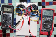
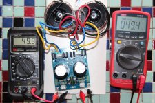
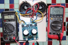
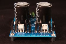
Soldered up and tested the PSU meanwhile. 41,5 AC sec unloaded, about 49,5 VDC@127 mA (390R dummy) and 48,5@145mA (335R). Might eventually sneak up to the 50 depending on the final setting. Am I clear with that or do I need to us the RD/Link?
Attachments
What output voltage do you get at maximum supply voltage as the input?
Do you meen unloaded, with just the C and the bleeders?
- Home
- Source & Line
- Analogue Source
- Simplistic NJFET RIAA