Hi AndyCan you provide more of an explanation about this? For instance:
Q1: what causes "Miller capacitance"?
Q2: is the effect of having "Miller capacitance" that you have to decrease the value of either C1 or C2 in the (passive) RIAA network, to compensate (so you end up with the correct values, according to the RIAA equations)?
Q3: can you calculate the expected Miller capacitance value?
Thanks,
Andy
Second stage input capacitance (Miller) is parallel to the Riaa caps so it must be taken in consideration while designing the filter.
We can calculate the miller capacitance but we end up only with an aproximation.... real values must be measured with dedicated equipment or else, riaa caps must be fine tuned by hear
")
Anyway it is all system dependent
Hi SantosWhat do you mean with lossy capacitors? PIO?
IMO, styroflex or MKP are very good for the riaa filter... just make sure you get a good match between channels and the simplistic will sing
Do not use PIO caps... they sound too rounded and the magic is gone.
You can trim larger caps with smaller styroflex or very small SM (Only use good quality SM).
For coupling cap you can rely on a good teflon from russia.
On the output an average MKP (like Mundorf MKP or Auricap) bypassed by a 100n Obbligato gold can give you good results.
If you use a large obbligato gold on the output, do not bypass it.... these are really good as is
Hi Andy
Second stage input capacitance (Miller) is parallel to the Riaa caps so it must be taken in consideration while designing the filter.
We can calculate the miller capacitance but we end up only with an aproximation.... real values must be measured with dedicated equipment or else, riaa caps must be fine tuned by hear
Anyway it is all system dependent
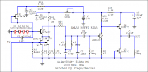
Just a cascoding JFET did not reduce it very drastically as your RIAA HF cap tweaked to lower indicates in folded input experiment. That and the low Vds it inevitably provides VS solo JFET probably means this secondary to test addition is only more JFETs and no good, I will leave it out. The real change is the input stage design. So your test circuit basis without BF245C:
Attachments
Hi Andy
Second stage input capacitance (Miller) is parallel to the Riaa caps so it must be taken in consideration while designing the filter.
We can calculate the miller capacitance but we end up only with an aproximation.... real values must be measured with dedicated equipment or else, riaa caps must be fine tuned by hear
Thank you for the explanation, RCruz.
Regards,
Andy
Hi Salas
The Wallis experiment is now a full on simplistic... you have e-mail.... GRAND
Time I put one under the iron to listen too. Thanks for good build early testing. Mine will be 63dB with 2x 2SK369 because I will use DL103R.
Just a cascoding JFET did not reduce it very drastically as your RIAA HF cap tweaked to lower indicates in folded input experiment. That and the low Vds it inevitably provides VS solo JFET probably means this secondary to test addition is only more JFETs and no good, I will leave it out. The real change is the input stage design. So your test circuit basis without BF245C:
Thank you Salas
BTW, I am using 1k4 for R11... the rest is as in the schematic.
Been listening to it for a while now.... Improved dynamics with great credibility... no harshness... very musical like the "normal" simplistic but with some added mid range detail and speed... Special
Can become something outstanding with some care and a good choice of components.
Who knows after big blue transplant even? Maybe one step beyond?
Madness - One Step Beyond - YouTube
Madness - One Step Beyond - YouTube
BTW, I am using 1k4 for R11... the rest is as in the schematic.
How much VDC from 1K4's right side to capacitor and ground?
Hi Salas,
In looking at your initial schematic again, I notice you have used a 47K resistor leading into the RIAA network.
I have seen a 22K resistor used instead, in other similar JFET designs. Can you explain the reason why you chose 47K?
I know that changing this value will require a change to the values of the RIAA components but this is not a problem and I was thinking maybe the lower value would reduce the signal loss which occurs in the RIAA network?
Thanks,
Andy
Its chosen to be high enough to not tax the first stage's Zo & current drive capability, and to result in typical RIAA capacitor values. I had used 22K for instance when I had 4 JFETs thus huge current reserve from bias in a low MC, led to smaller load resistor (lower Zo), plus a number of caps 33n to utilize. ~100n shunted bass triplet and 33n HF cap. Current for capacity defines slew rate also. Its about some good judgement act mostly.
Its chosen to be high enough to not tax the first stage's Zo & current drive capability, and to result in typical RIAA capacitor values. I had used 22K for instance when I had 4 JFETs thus huge current reserve from bias in a low MC, led to smaller load resistor (lower Zo), plus a number of caps 33n to utilize. ~100n shunted bass triplet and 33n HF cap. Current for capacity defines slew rate also. Its about some good judgement act mostly.
Thanks, Salas,
I asked because someone told me that a lower value resistor would generate less noise ... which might be a good thing in a phono stage.
Regards,
Andy
Having more capacity to charge will be much more of a detail loss concern, and don't forget, this is passive. Its like having a -20dB voltage divider after signal and noise. I have checked that, it does not add noise. Input stage dominates all stages for noise in fact when certain ratios are taken into account. No worries as you say in Oz.
Hi Santos
IMO, styroflex or MKP are very good for the riaa filter... just make sure you get a good match between channels and the simplistic will sing
Do not use PIO caps... they sound too rounded and the magic is gone.
You can trim larger caps with smaller styroflex or very small SM (Only use good quality SM).
For coupling cap you can rely on a good teflon from russia.
On the output an average MKP (like Mundorf MKP or Auricap) bypassed by a 100n Obbligato gold can give you good results.
If you use a large obbligato gold on the output, do not bypass it.... these are really good as is
At the moment I thinking about using either the vishay 1837 or multicap for riaa positions with fine tuning using styroflex and obbligato for interstage and output coupling.
My fluke 179dmm only measures capacitance down to 1nf so I can't measure with enough precision the riaa caps but Parts-connection does have a matching service for capacitors so I might ask them to measure and match the capacitors and send me the data so I fine tune with the styroflex if needed.
I there a way I can measure the capacitors with some sort of simple circuit as we do for idss in transistors?
The 179 is 1.2% plus 2 counts, good to know that your matches are good between channels at least relative to the meter which is something. Your absolute value, no, it can't say. Needing an order of magnitude better measuring accuracy than 1% caps to say what they are absolutely. But, academic in our case. 1% caps are enough. If they are to charge an arm and a leg for measuring say 5% caps, get Vishay, they are cheap and small, and you save for a silver in oil interstage coupler for instance. Get it 47nF to be cheaper and smaller, this one's influence you will more probably hear. Or save for vinyl and beer. Which is maybe the better plan.
Hi MASantos
You can try putting several caps in test together...
...of known values...that your meter can measure.
Then subtract the results, a few times, get some referances & bearings...
...and then you can measure smaller values...
...knowing the data you already have from the bigger values.
Might be worth trying.
Can be a usefull way to measure smaller Ohms as well, without a specialist meter.
Si.
PS you can almost 'guarantee' polystyrenes & silver-micas of small 1% or pF tolerance will be spot-on enough.
- Home
- Source & Line
- Analogue Source
- Simplistic NJFET RIAA