It works ok with MF or CF but I keep having startup issues with some of my builds.
I found that there is an inductive interaction that sometimes happens, so the shunt only starts if I touch the connection between R2 and Q2.
It is not common and I already built 14 V12R without any issues. Once it happens I need to redo R2 placement until I get it working perfectly.
I am not sure what causes this behaviour and initially I believed it was related with resistor type or value but now I am not sure.
Once I experimented with 140r instead of 120r and it did not solve the problem. maybe someone experimented with lower values (80r ?)
I am very interested in your layout that is quite different from mine so I would like to know if you had any similar issues.
Q3,Q4, associated bias resistors and LED. If the output won't catch up fast due to layout parasitics, it won't bias up the cascode to ignite the CCS well. That is why even a non optimum layout can kick start with a probe touch. Also some transistors can have bit higher capacitance than the next sample.
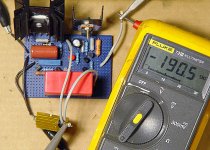
Shunt operational!
I Salas (et al)-
I wired up my 1.2R shunt and fed it power. Loaded output with 1kohm, as you instructed.
Results-
Input- 44.0vdc
Output-
Varied from 37vdc to 42vdc in 1 v steps.
Always consumed 188.3 to 188.6mA (after a little settling time).
IRFP9240 and load R were warm to the touch. IRF9610 was lukewarm.
At 43.5v, current starts to drop.
At 44.0v, 113.9mA
At 44.6v, current bottoms out at 56.9mA.
Scope observations-
Tek 20 mHz scope. I am limited as I only have 100:1 probe, so max sensitivity is only 500mA/division.
No sign of oscillations at the output, across load resistor at any frequency.
So, is 500mA/div sensitive enough?
I'm traveling for the US holiday this week, will be back next week to continue working on the RIAA. Pics of shunt so far, below. Temporary power wiring and sinks.
Cheers! -Kent
Attachments
check the voltage across the current setting resistor in the CCS.Input- 44.0vdc
Output-
Varied from 37vdc to 42vdc in 1 v steps.
Always consumed 188.3 to 188.6mA (after a little settling time).
IRFP9240 and load R were warm to the touch. IRF9610 was lukewarm.
At 43.5v, current starts to drop.
At 44.0v, 113.9mA
At 44.6v, current bottoms out at 56.9mA.
When Vin-Vout >~5V, you should find that the resistor Vdrop is substantially constant.
When Vin-Vout <~5V you will find that resistor Vdrop is falling rapidly as Vout closes in towards Vin.
The Shunt is reducing it's shunt current to try to maintain Vout. Effectively your expensive CCS+Shunt regulator is not being allowed to do it's job properly.
The earlier Salas Regs had a recommendation of Vin-Vout >7Vdc for all operational conditions.
What is the recommendation for V1.2?
CorrectionIt works ok with MF or CF but I keep having startup issues with some of my builds.
I found that there is an inductive interaction that sometimes happens, so the shunt only starts if I touch the connection between R2 and Q2.
It is not common and I already built 14 V12R without any issues. Once it happens I need to redo R2 placement until I get it working perfectly.
The stubborn shunt fires when I touch R3 on Q3 side (Not R2 Q2 as I stated before)
I usually solve this issue by moving R3 and not R2.
Last edited:
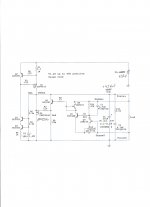
I think what is happening is that your finger is injecting a small pulse to turn on the CCS FET.shunt fires when I touch R3 on Q3 side
A resistor + Zener across DS of the CCS FET may solve this turn on fault.
Maybe try 12V or 15V Zener and a 1k or 2k resistor.
At start up when Vout = 0Vdc and Vin = 52Vdc, with the FET OFF, the Zener will pass 18.5 to 40mA. A couple of mA will turn ON the cascode by developing a LED voltage and the remainder of that start up current starts to charge up capacitances downstream of the CCS.
Once the FET turns ON, the Vout will rise from 2 or 3Vdc to 42Vdc.
The Zener current should now be zero mA and the circuit should work normally.
Probably not the best way to ensure reliable start up. Can someone see a better way?
Will this R+Z be completely innocuous, once the CCS has established correct current?
Last edited:
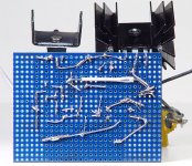
Thank you... Now can you please post the layout or pictures of the shunt ?
I would like to compare the positions of R3 and Q3 in your shunts with mine")
Pic
Attachments

I think what is happening is that your finger is injecting a small pulse to turn on the CCS FET.
A resistor + Zener across DS of the CCS FET may solve this turn on fault.
Maybe try 12V or 15V Zener and a 1k or 2k resistor.
At start up when Vout = 0Vdc and Vin = 52Vdc, with the FET OFF, the Zener will pass 18.5 to 40mA. A couple of mA will turn ON the cascode by developing a LED voltage and the remainder of that start up current starts to charge up capacitances downstream of the CCS.
Once the FET turns ON, the Vout will rise from 2 or 3Vdc to 42Vdc.
The Zener current should now be zero mA and the circuit should work normally.
Probably not the best way to ensure reliable start up. Can someone see a better way?
Will this R+Z be completely innocuous, once the CCS has established correct current?
Hi Andrew
It seems reasonable and logical.
what would be orientation of the zener ?
Last edited:
Thank you so much Merlin
Do you have resistors under the board ?
- Home
- Source & Line
- Analogue Source
- Simplistic NJFET RIAA