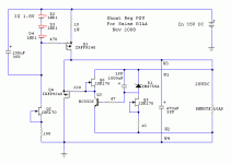
I am strugling with heatsinks....
Would this one be suitable for the shunt ? H S MARSTON - 05DN-00500-A-200 - HEAT SINK, 4.5°C/W http://pt.farnell.com/jsp/search/productdetail.jsp?sku=414189
Or two of those (one per mosfet) AAVID THERMALLOY - 6398BG - HEAT SINK, TO-220/218, 4.4°C/W
http://pt.farnell.com/jsp/search/productdetail.jsp?sku=1213473
Ricardo
RCruz said:I did a new layout so I can fit the individual heatsinks....
I calculated a led string dropout of 6,39v, using 14r I have ICCS with load = 174 mA
Using R1 = 10, I get 259mA... is this viable ?
Ricardo
Depends on the Vgs of the exact part, but with such Leds I would surely use the 14R so not to overshoot 200mA.
Yes if Vgs will be like that. You just measure the drop across the resistor in the end, and if its non usefully excessive, you make it higher R. I prefer the yellows slightly for best noise also. Its that the greens are easier to predict for those they don't match them.
RCruz said:Hi Salas
After several hours designing.... I hope you agree with this layout.
It will surely work. Its better than the previous one. With very short and twisted cables to the load. But what Andrew says is that if you are going to make a PCB, you can make it with nodes ready for ''remote sensing''. The benefits are, that the reference and driving circuit can ''sense'' and correct for the cable to the load impedance. That becomes more critical if you put the shunt in another box with a transformer, or even for vaporizing the short length if near. There is some benefit in perfection, if near the load just incremental, but you are to decide. Here is the remote sensing with 4 wires for the V1 shunt.
Attachments
newbie need help
Hello to all,
I built one channel of these 2 circuits:
By net_urbano
By net_urbano
the rectifiers diodes, the bulk C 10000uF, the shunt and the RIAA are together all on a single perforated board.
Before to build the second channell, for try, i connect the output of the riaa to a stax srm-313 headphone amplifier. What I hear in headphones is a very thiny music and a big hum. Reading the thread I saw that Thomo had a similar problem to mine and Salas suggested to measure some voltages because it is possible that last Q (buffer NJFET) has higher than calculated Idss and drops its Vd too much, Vg under its Vs, so it won’t work.
First of all I checked all the wiring, and all the parts are correctly oriented.
Than i measured some voltages:
Q5: VD = 17,7V; VS = 6,83V (OK?); VG = 6,80V (BAD);
Q3 BASE = 7,62V (OK?); Q3 COLLECTOR = 15,07V (OK; PSU = 24,6V)
Q1: VD = 6,96V (OK)
The Idss of Q5 is 9,7mA so i changed it with another one with Idss = 8mA but the problem remains the same. Big hum, no music. Q5 Vs is now = Q5 VG: 6,72V.
Can someone help me ?
Luca
Hello to all,
I built one channel of these 2 circuits:
An externally hosted image should be here but it was not working when we last tested it.
By net_urbano
An externally hosted image should be here but it was not working when we last tested it.
By net_urbano
the rectifiers diodes, the bulk C 10000uF, the shunt and the RIAA are together all on a single perforated board.
Before to build the second channell, for try, i connect the output of the riaa to a stax srm-313 headphone amplifier. What I hear in headphones is a very thiny music and a big hum. Reading the thread I saw that Thomo had a similar problem to mine and Salas suggested to measure some voltages because it is possible that last Q (buffer NJFET) has higher than calculated Idss and drops its Vd too much, Vg under its Vs, so it won’t work.
First of all I checked all the wiring, and all the parts are correctly oriented.
Than i measured some voltages:
Q5: VD = 17,7V; VS = 6,83V (OK?); VG = 6,80V (BAD);
Q3 BASE = 7,62V (OK?); Q3 COLLECTOR = 15,07V (OK; PSU = 24,6V)
Q1: VD = 6,96V (OK)
The Idss of Q5 is 9,7mA so i changed it with another one with Idss = 8mA but the problem remains the same. Big hum, no music. Q5 Vs is now = Q5 VG: 6,72V.
Can someone help me ?
Luca
- Home
- Source & Line
- Analogue Source
- Simplistic NJFET RIAA

