Hi Salas
Found the issue... I am sorry to report I placed some 6k8 in R1 instead of 6.8r
Now it is steady as a rock and very warm (100ºC).
I will implement it today and report the differences.
Ricardo
PS:
I read you have a capacitor-less B1... I am very interested... Would you care to share the idea ?
Found the issue... I am sorry to report I placed some 6k8 in R1 instead of 6.8r
Now it is steady as a rock and very warm (100ºC).
I will implement it today and report the differences.
Ricardo
PS:
I read you have a capacitor-less B1... I am very interested... Would you care to share the idea ?
2nd shunt installed !!!
Noticeable gains in transient speed and attack.
Bigger image and better focused and tighter bass.
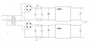
All this using only one bridge before a 10.000uF cap.!!!
This Riaa design really benefits from a good psu.")
Next will be the double bridge + cap setup.
PS: I rolled back from the output cap bypass (The teflon gave enourmous extension in bass but also in the trebble and I found it too much for the actual setup)
Ricardo
Noticeable gains in transient speed and attack.
Bigger image and better focused and tighter bass.
All this using only one bridge before a 10.000uF cap.!!!
This Riaa design really benefits from a good psu.
Next will be the double bridge + cap setup.
PS: I rolled back from the output cap bypass (The teflon gave enourmous extension in bass but also in the trebble and I found it too much for the actual setup)
Ricardo
After 1 hour burning..... incredible instrument placement and diferentiation. Deeper sounstage.
Working in the CDP, I learned that best results are obtained by placing 1 reg near each power v-in of each chip so now I have 11 regs in the CDP (several chips have more than 1 reg). Each one gave enourmous gains.
It seems here we have a similar situation. (But incomparably superior results)
Ricardo
One mod a day keeps the doctor away....
Nice Ricardo. I have experienced similar gains in Michael's double PSU one that I have shown here before. I would suggest you make an experiment about cutting on dissipation a little and see if your sound is still the same. Try to listen with 8R2 and 10R shunt's R1 at a point.
RCruz said:PS:
I read you have a capacitor-less B1... I am very interested... Would you care to share the idea ?
Its in the main B1 thread.
Its revised schematic is there too.

I am noticing an unwanted increase in hum... right channel... now powered by the new shunt "b" coloured brown.
There is a lower freq noise in this channel (it is buried beneath the surface disc noise but audible when the pickup is not lowered)
The other channel also produces noise but not so audible in low freq.
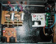
Seems to me I have a placement issue.... must I build a gnd screen between the shunt and riaa boards ?
There is a lower freq noise in this channel (it is buried beneath the surface disc noise but audible when the pickup is not lowered)
The other channel also produces noise but not so audible in low freq.
Seems to me I have a placement issue....
must I build a gnd screen between the shunt and riaa boards ?Attachments

RCruz said:it happens with both channels.
It was not unbearable before the second bridge was added.
You have to revise your grounding. Start with breaking one channel's ground return to star with a 10R and see if that helps. If not, make a diagram with your grounding scheme and post it here so we can all think about the loop.
Just solved the issue.
I was connecting GND from bridge+smoothing cap to shunt and then to star GND.
Now I have the smoothing cap connected to star GND and shunt also connected to star. (Between smoothing cap and shunt I have only the +Vin lead)
No more hum.... sound is very good.... in fact is better because the hum has always been present but I only found it unbearable after placing the second bridge+cap+shunt.... (Sometimes you need to go under to really be able to fly !)
I must find a simple way to post hand drawings.... using word is a pain.
Ricardo
I was connecting GND from bridge+smoothing cap to shunt and then to star GND.
Now I have the smoothing cap connected to star GND and shunt also connected to star. (Between smoothing cap and shunt I have only the +Vin lead)
No more hum.... sound is very good.... in fact is better because the hum has always been present but I only found it unbearable after placing the second bridge+cap+shunt....
(Sometimes you need to go under to really be able to fly !)I must find a simple way to post hand drawings.... using word is a pain.
Ricardo
it must be done this way.RCruz said:Just solved the issue.
Now I have the smoothing cap connected to star GND and shunt also connected to star. (Between smoothing cap and shunt I have only the +Vin lead)
The star ground is the voltage reference.
If the shunt or any sensitive circuit shares the main current carrying trace/wire with the PSU to star ground then the big currents will create voltage contamination of the low level signals.


- Home
- Source & Line
- Analogue Source
- Simplistic NJFET RIAA