I'm years late to the party, but I finally got around to building the Ultra FSP. I've built the second and third editions of Wayne's Pearl, and most recently had been listening to the Softone Model 4 tube-based phonostage. In my mind the Softone represents one side of the coin very well (tube based, zero NFB), and the recent Pearl 3 represents the other side nicely(discrete/opamp combo, NFB). Ultra FSP sounds like a perfect blend of the two. Love it!
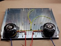
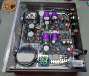
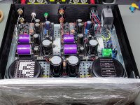
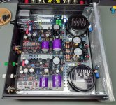
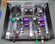
Everything went together without a hitch, thanks in large part to Teabag's painstakingly curated kit. I used some film caps I already had on hand, hence the bit of overhang on C4. I repurposed on old 1U chassis, so I had to make a few cap swaps to fit the case. Its a very, very quiet phonostage. I initially used regular twisted pair wiring for the DC, but later switched to some screened wiring I recycled from an old Apple computer supply (It was quiet both ways). At some point I may use some screened wiring for the signal, but for now I'm happy.
ExcellentOutstanding build!! Very nicely done.
")
👏 👏
Ninety percent of the work was done last year but only this weekend it was put to work.
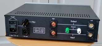
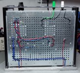
Let me remind the reader. You do not want to have the PSU in the same chassis of the phono. My plan from the beginning was to use the one-box solution in my living room where strict aesthetics criteria are in place (hence the size and the single box) with a basic MM cartridge. When I will have a dedicated room (a dream more than a plan), I will upgrade cartridge and use an external RAW PSU (notice the switch and DC connector in the back). And maybe move the phono back and forth between the two systems.
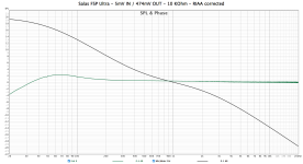
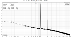
Do not mind too much the measurements. I just wanted to check gain (with a couple of settings) and if any serious issue with noise and hum would show up. It seems some 50 Hz is picked up. Measurable, of course, but it does not seem to be an issue in the current system. Actually, I never had a more silent phono before. I need to put the volume knob to 75% to start hearing first some hiss and then a faint hum. Listening levels never pass 50% volume (I have both too much gain and annoying neighbours).
I listened to just a couple of records at low volume while the child was asleep and the rest of the family out. No way to compare to anything since last time I listened to a record was last year and with a tube-based phono. But you feel that there is structure and solidity in the sound. Plenty of dynamics and articulation and certainly no lack of bass.
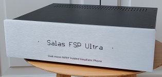
This is another great example of what a short signal path (along few selected parts) can do to music reproduction, and what a talent is needed to design such circuitry. Thank you again Salas!
A final note on the build. I like to source parts by myself. In this case it would have been very difficult to source the JFETs and impossible to beat Tea-Bag matching and part selection. You have been warned.
Let me remind the reader. You do not want to have the PSU in the same chassis of the phono. My plan from the beginning was to use the one-box solution in my living room where strict aesthetics criteria are in place (hence the size and the single box) with a basic MM cartridge. When I will have a dedicated room (a dream more than a plan), I will upgrade cartridge and use an external RAW PSU (notice the switch and DC connector in the back). And maybe move the phono back and forth between the two systems.
Do not mind too much the measurements. I just wanted to check gain (with a couple of settings) and if any serious issue with noise and hum would show up. It seems some 50 Hz is picked up. Measurable, of course, but it does not seem to be an issue in the current system. Actually, I never had a more silent phono before. I need to put the volume knob to 75% to start hearing first some hiss and then a faint hum. Listening levels never pass 50% volume (I have both too much gain and annoying neighbours).
I listened to just a couple of records at low volume while the child was asleep and the rest of the family out. No way to compare to anything since last time I listened to a record was last year and with a tube-based phono. But you feel that there is structure and solidity in the sound. Plenty of dynamics and articulation and certainly no lack of bass.
This is another great example of what a short signal path (along few selected parts) can do to music reproduction, and what a talent is needed to design such circuitry. Thank you again Salas!
A final note on the build. I like to source parts by myself. In this case it would have been very difficult to source the JFETs and impossible to beat Tea-Bag matching and part selection. You have been warned.
Attachments
-
 2023-07-14 16.31.40.jpg692.8 KB · Views: 135
 -
 2024-02-10 09.29.43.jpg250.6 KB · Views: 134
 -
 2024-02-10 09.29.04.jpg281.4 KB · Views: 138
 -
 2024-02-09 - Salas FSP Ultra - Frequency - RIAA corrected.png33 KB · Views: 153
 -
 2024-02-09 - Salas FSP Ultra - FFT.png49.6 KB · Views: 166
 -
 2024-02-08 17.54.29.jpg752 KB · Views: 173
 -
 2024-02-08 17.54.06.jpg635.4 KB · Views: 167
 -
 2024-02-08 17.53.44.jpg830.3 KB · Views: 164
 -
 2024-02-08 17.52.53.jpg768.9 KB · Views: 154
 -
 2024-02-02 15.52.58.jpg703 KB · Views: 146
 -
 2024-02-01 17.12.03.jpg852.5 KB · Views: 125
 -
 2023-07-14 16.38.34.jpg442.5 KB · Views: 131
Last edited:
For once it is the other way around! What an honour.Thank you for the photos, they are worth some study.
Last edited:
Thanks! I used software for the RIAA correction in REW adding the RIAA curve as calibration file after the measurement. I did try both the divider and without. I could not see much of a difference with the soundcard (plot is without) but it was a clear improvement with the signal generator and oscilloscope.
Software correction is a good accurate method. Only you can't use squarewaves evaluation when its not a hardware anti-riaa. What soundcard you used? Normally a 100 times divider, say 1k series 10Ω parallel, gives less signal source noise in any case. Because the noise gets cut down as much as the signal itself. 500mV RMS to the divider for 5mV out or 100mV for 1mV etc. It gets more apparent as you progressively go with smaller signal testing the MC modes. If you will try again use dbV scale not SPL.Thanks! I used software for the RIAA correction in REW adding the RIAA curve as calibration file after the measurement. I did try both the divider and without. I could not see much of a difference with the soundcard (plot is without) but it was a clear improvement with the signal generator and oscilloscope.
This is my FFT, near 300mV RMS phono output for 0.25mV input (50mV calibrated generator output level through 1k:5Ω divider, setting LMC).It’s nice to see the FFT, thanks for sharing. I honestly haven’t scoured the thread for other measurements - do these appear accurate for a proper implementation?
Peppe, any chance you could share that RIAA cal file?
Here's some filter curve data:
# RIAA Standard Response Normalized to 1 KHz
# Edited by Salas produced from time constants
#
20, 19.36
28, 18.83
40, 17.88
50, 17.03
63, 15.94
80, 14.59
100, 13.18
160, 9.90
200, 8.31
315, 5.27
400, 3.87
500, 2.74
800, 0.84
1000, 0.09
1500, -1.31
2000, -2.50
3000, -4.65
4000, -6.52
5000, -8.12
6100, -9.64
8000, -11.81
10000, -13.65
15000, -17.07
20000, -19.53
I would also like to learn how to do proper phono stages measurements. This thread is where I found more information than any other place.It’s nice to see the FFT, thanks for sharing. I honestly haven’t scoured the thread for other measurements - do these appear accurate for a proper implementation?
Peppe, any chance you could share that RIAA cal file?
The RIAA file I used is in attached. It looks like it matches Salas values with just some more data points.
I have a cheap anti-riaa rig. I did not use it this time. I must find it. My soundcard is an old Echo Audiofire 4 connected via the old good FireWire to an even older MacBook. I have used a 10K series 100R parallel divider but at the end I only measured MM. And yes, I usually make different screenshots with different scales. Not this time. SPL with mic-calibration takes the fundamental to 0dB and is the first I look at. But noted!Software correction is a good accurate method. Only you can't use squarewaves evaluation when its not a hardware anti-riaa. What soundcard you used? Normally a 100 times divider, say 1k series 10Ω parallel, gives less signal source noise in any case. Because the noise gets cut down as much as the signal itself. 500mV RMS to the divider for 5mV out or 100mV for 1mV etc. It gets more apparent as you progressively go with smaller signal testing the MC modes. If you will try again use dbV scale not SPL.
Same here.my ears suggest it’s working just fine
Attachments
Last edited:
We make sure that the divider's input value does not challenge the soundcard's output ability/impedance. The divider's output value must not be overloaded by the phono's selected impedance too. If we load a hundred Ohm output divider with a hundred Ohm MC load setting we get half the signal we expect for example. Keep a 10x difference or more. If we have a calibrated sensitive AC voltmeter we can also verify the few mV or below mV test signal level at the phono's input.
We must use coaxial cable and the division resistors must be shielded in a full metal male RCA at the phono's input end. We should investigate what is the line input impedance of the soundcard so the 2.2uF output capacitor does not create a steep filter with it. 20kΩ or higher is good enough. We take impedance into account for reading the very low frequencies region response correctly.
We select line-in, not mic-in which is too low Z. We don't add input gain with the soundcard's knobs. It introduces noise and also wrongs the Y scale. We keep them at zero position. We always perform the line level Cal routine for the soundcard/interface in the testing software on zero line input gain knobs position.
Thanks for the pointers. I’ll take proper care in constructing the divider. I’m using 1k load and LMC gain, so will shoot for something at/below 100R. I may just use your same 1K/5R. Using a Focusrite Scarlett for sound card and will verify its input impedance too.
dBc (decibel carrier) mode gets your peak band to zero ref too. dBV is directly readable for level vs 1V RMS zero ref. This phono (as the majority of such devices) is designed for around -10dBV consumer level nominal output i.e. 300mV RMS. Can always achieve at least that, even with some weaker output MM cartridge models.SPL with mic-calibration takes the fundamental to 0dB and is the first I look at. But noted!
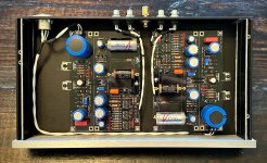
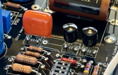
Got my boards transferred to a new, dedicated chassis. About as small as I could go at 1U 330x170. I also settled on some final caps and values for the EQ portion. Ended up with two little Amtran copper foils in parallel to get me right at 15.2nf for the HF. I also swapped in some CDE 716P (polyprop and foil orange drops) for the LF. Couldn't be happier and am checking this one off as 'DONE.' For sure my #1 phonostage!
Attachments
I have a cheap hardware inverse RIAA too. The iR 100 from Cyprus. Its on eBay. It includes 3.18us Neumann though, follows the Hagerman norm. Expect -0.65dB textbook deviation at 20kHz through a nominal RIAA phono. And rounder 10kHz squarewaves.I have a cheap anti-riaa rig. I did not use it this time. I must find it.
I replaced its original caps with C0G 1% and its flat enough against record side RIAA curve test if it also accounts for Neumann. Say +/-0.15dB with full test rig uncertainties included. The MOTU audio interface I use drops a wee bit towards the spectrum ends anyway. iR wasn't doing too bad with the original mini film caps either.
- Home
- Source & Line
- Analogue Source
- Simplistic NJFET RIAA