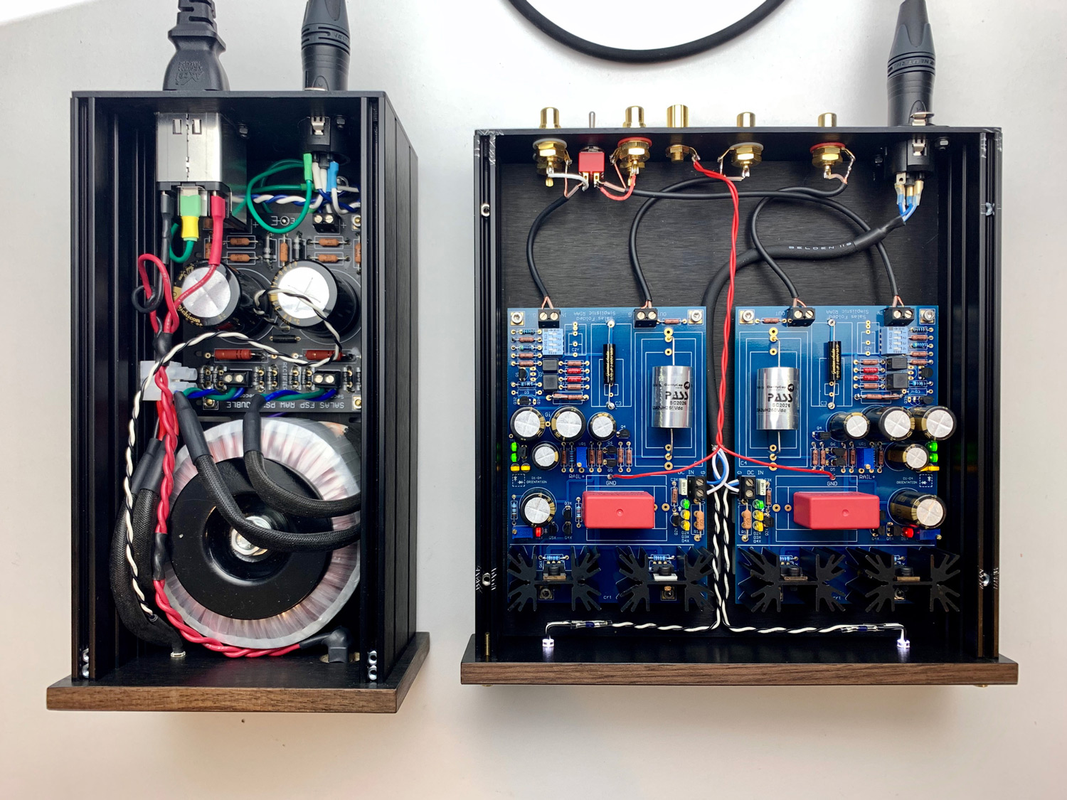
Yes for PSU—tight, but works, I fit the amp into a 1U 230x230—shorter sinks and pay attention to cap heights. Worked out great.
I go for as compact as I can though. It's a fantastic amp—wouldn't really dream of a different one. Except the new version...
I go for as compact as I can though. It's a fantastic amp—wouldn't really dream of a different one. Except the new version...
Attachments
For power connections, will this be ok? It is locking....
Neutrik Connector NC4FD-L-1 4 Pin XLR Female
Neutrik Connector NC4FD-L-1 4 Pin XLR Female
Awesome, thanks.
I just realized that my transformers will have to be mounted on their sides to fit in the box. Their width dimension will be in the box height direction. Size Length 79 × width 68 × height 39(mm) Weight: 0.56kg
High-End 30W / 30VA R-Core Transformer PRI 115V/230V 50/60Hz SEC 18V+18V | eBay
I just realized that my transformers will have to be mounted on their sides to fit in the box. Their width dimension will be in the box height direction. Size Length 79 × width 68 × height 39(mm) Weight: 0.56kg
High-End 30W / 30VA R-Core Transformer PRI 115V/230V 50/60Hz SEC 18V+18V | eBay
For umbilical cords, I use Lumberg brand (something like SV40) for mail and relevant panel-mounted females. You can choose witch one goes for male/female side by model number. I prefer male for panels and females for cord for safety purposes.
These are very high quality industrial connectors.
These are very high quality industrial connectors.
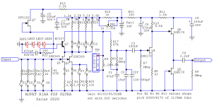
FSP ULTRA schematics
Sensitivity setting (S5-S12)
-------------------------------
MM 40dB
S8 ON S12 ON all others OFF
HiMC 43dB
S7 ON S11 ON all others OFF
MC 56dB
S6 ON S10 ON all others OFF
LoMC 62dB
S5 ON S6 ON S9 ON all others OFF
CAUTION! Don't switch S5-S12 when the phono is powered on.
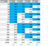
Input Load setting (S1-S4)
------------------------------
Rx1-Rx4 install preferred values
S1-S4 all OFF input load is 47k
S1-S4 choose load by ON each Rx
(or by parallel ON combinations)
CAUTION! Don't switch S1-S4 when the system volume is open.
Test point setting procedure
--------------------------------
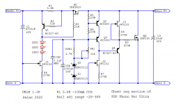
UBiB 1.3S section VR1 adjusts the rail voltage. Start with +34V
Then trim the phono's other local VR1 towards a 4V T.P reading
If not yet reachable readjust rail voltage until hitting 4V T.P goal
Each sensitivity has a different bias balance. Redial T.P for each.
30-34V rail range is not unusual between MM to LoMC configs.
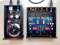
Board dimensions
--------------------
152x107mm Phono+Shunt Reg 1.3S
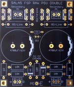
95x80mm Raw PS
Bill of materials: BOM link
GB thread: GB link
Sensitivity setting (S5-S12)
-------------------------------
MM 40dB
S8 ON S12 ON all others OFF
HiMC 43dB
S7 ON S11 ON all others OFF
MC 56dB
S6 ON S10 ON all others OFF
LoMC 62dB
S5 ON S6 ON S9 ON all others OFF
CAUTION! Don't switch S5-S12 when the phono is powered on.
Input Load setting (S1-S4)
------------------------------
Rx1-Rx4 install preferred values
S1-S4 all OFF input load is 47k
S1-S4 choose load by ON each Rx
(or by parallel ON combinations)
CAUTION! Don't switch S1-S4 when the system volume is open.
Test point setting procedure
--------------------------------
UBiB 1.3S section VR1 adjusts the rail voltage. Start with +34V
Then trim the phono's other local VR1 towards a 4V T.P reading
If not yet reachable readjust rail voltage until hitting 4V T.P goal
Each sensitivity has a different bias balance. Redial T.P for each.
30-34V rail range is not unusual between MM to LoMC configs.
Board dimensions
--------------------
152x107mm Phono+Shunt Reg 1.3S
95x80mm Raw PS
Bill of materials: BOM link
GB thread: GB link
Attachments
Nice! I like the new design, especially all the switches. If one populates the Ultra FSP for use with MM carts only different values for Rx1 - Rx4 might be useful. I use the following configuration of resistor values: https://www.muffsy.com/phonostage-impedance.html
What was the reason for you to use BC-327 for Q3 instead of BC-560? What hfe range of BC-327 is recommended?
What was the reason for you to use BC-327 for Q3 instead of BC-560? What hfe range of BC-327 is recommended?
Attachments

Loading resistors are up to you. Those schematic values are just an example. Steady 47k R1 for MM and the Rx1-Rx4 switchable others are typical for MC & LMC as shown.
To build the example and expecting it to work correctly you have to be literal for the noted JFETS IDSS though. If of other IDSS their source pin resistors have to change too as you know. If the 2SK369s especially will end up with inadequate enough Id in circuit, the folded cascode input stage can totally shut down for signal. That is what T.P adjustment is for.
Those things are well detailed in the previous build guide. A must read. This one has the same circuit heart. Works the same, boards connect the same between them, ground wiring is done the same. Gain switching facilities, new printed board layout, shunt reg version, sinking style, are their differences. A further RC local filter cell was added too but that's minor.
A major PITA is when having an ever depleting JFETs stash to pick from. For two channels all JFETS the same in same positions (!). Tea for instance uses a jig mimicking live phono's two last stages bias voltages for maybe two years now. Not only for IDSS matching from a wider variety than the example's but to also specify their proper R8 R11 partners included in his mini-kits. This is Shaolin level parts sorting stuff.
Regarding your BC560 question:
I always wanted high Hfe but also lower rbb' (thus lower self noise) for Q3 if possible. BC560C was great for the Hfe priority but not stellar in 1/f self noise spec. For that reason in the previous version there was the NOS Toshiba 2SA970BL option too (Q3Z). After I had seen later tests of BC327-40 (high Hfe class) proving well balanced for Hfe & 1/f noise, I simplified the new layout for accepting just one type. Since it had to be tighter because of the extra DIP switches.
Not that I could see some distinctive impact in noise measurements of the whole phono but anyway.
BC560C still lives on in specific positions of the shunt regulator section because fast, but it was recently shut down by all major manufacturers as well.
No big news to UFSP though, because this legacy semis phono was designed right from the start around much harder to find genuine NOS semiconductors anyway. All needed transistor types are secured for the GB needs at least.
This is not cheap, fast, or Lego easy. Both its active and passive parts are very expensive. The semis sourcing and matching... hell.
Not a beginner's project, that's well understood. Few are made once in a while. It had been discontinued but enough kept on pressing for its return. So I gave it a honorary modern repackaging. And it was consuming. But I hope to have made you guys happy. For as long as its core parts genuine stock lasts.
Yes I would agree. As you know i am fiddling with basic versions of the pacific phono circuit since a few years. Main reason was that FSP looked too complex and expensive to me as a noob. I did not understand much of the posts in this thread either. After years of prototyping pacific phono stages, things started to improve when i added the buffer stage that i saw in this thread. Now i added the LED biased telescopic cascode and things improved again.
After some years (and literaly $600 spent trying to avoid the initial costs of a Salas FSP) i am more then ready to finally buy your well-made PCB to solder a kind of "final" Version. So i am grateful for this new possibility. Good thing is that i have most of the needed components in my parts bin already.
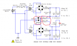
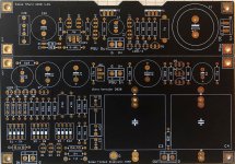
Yes, the yin yang diodes//10R loop break it some but still has reference at the raw psu chassis on mains earth. In a hard accident scenario the voltage rises above 0.6V on the 10R and the diodes conduct. The two 1R make the DC zero lines/signal grounds prefer the route to the phono chassis where they directly meet it at the TT gnd lug as they pass through the boards. If there is shield in the DC umbilical cable it should attach at one end only at the phono chassis. This scheme worked very well for many FSP builders as they mostly reported no hum loop problems with PE (protective earth) attached to the psu chassis. In case of a hum problem one of the two 1R can be lifted. There will still be DC zero lines meeting at the phono chassis.
... to help you end up broke once again
I just love that conclusion (and will quite probably follow that path)
[emoji1787]
It was reported done balanced with dual boards once here. If its mainly about wanting balanced output, also a transformer or THAT chip options can translate an SE output to XLR without boards doubling.
Although I have a friend who connects a conventional SE 57dB unit to a Boulder 2010 XLR preamp in pseudo balanced mode without apparent lack of drive. Its a matrix board build I made for him a long ago, before there was a PCB. The Riaa filter and stages coupling caps are handpicked NOS USA Teflon.
He is still using it as his main phono stage. I had the pleasure of listening to it again early this year after I updated its shunt regs to UBiB. It sounded tremendous in his system. Fed from a Clearaudio Goldfinger V2 cart.
Attachments
- Home
- Source & Line
- Analogue Source
- Simplistic NJFET RIAA