
Howdy, I’ve been loving this phono stage very much, but I’ve got a couple of fine tuning questions to ask. First, how long should I allow before the bias settles in? I’m still having to tweak it daily? Second, I’ve traced a channel volume imbalance back to the amp. When biased to 35V on the rail (+/- .25V for matching between boards) and both TPS dead on 3.6V, I’m reading a pink noise output of 2V vs 2.3V on the two boards. Is that normal with equal biasing, what is the likely cause of this, and what should I do to even that out? Otherwise getting very good results.
In MC mode each 2SK369 necessarily has a very low value resistor at the source pin. That allows them to wander because there's not much local feedback to counteract their temperature coefficient voltage drift like with the MM mode value.
Their DC setting does not affect the AC gain though. Its a centering condition that allows them voltage space above and below to deploy their signal. Which is much less than the DCV space, 50mV 1kHz with a 0.5mV nominal output cartridge.
So don't worry much, as long as there is ample voltage space around their DC point for signal, they will be happy. No matter if they wander that point somewhat, but not extremely, so not to bump on the stops.
If your pink noise source for measuring channel balance is a test record it won't be a verified accurate procedure to rely on. Starting from the record's unknown tolerances, going through the arm & cart geometry errors, ending at the cartridge's channel balance spec. A not too well leveled TT or wrong anti-skating are enough to compromise such a test anyway.
Do the following:
-Have a sine-wave generator. Even some function gen app on PC or mobile will do.
-Make it output 100mV RMS 1kHz. Your DMM in ACV mode should help you set that level.
-Put that signal through a voltage divider. 1k Ohm series 10 Ohm to ground.
-There's about 1mV clean enough signal across the 10 Ohm now. Send it to the phono's one input.
-Measure its corresponding output for AC signal level. Repeat the procedure on the other channel, note the results.
-Convert their voltage difference to dB. That's easier to quantify for audible impact. Dif=20*log10(V2/V1).
Now you know the true gain matching between the channels of your phono build. If there is an alarming difference in dB let me know to tell you what to check in the parts characteristics.
Very cool stuff there! Got a friend with a boatload of voltage generators, oscilloscopes and other test equipment. I just thought to test the output because it’s extreme enough that I have to adjust my power amp levels to equalize the channel levels, but this method will provide you some hard numbers to suggest adjustments. I should be able to get this done this weekend.
Hi Salas,
I am just wrapping up an FSP build and testing the raw PSU (from Teabag), and the rectified DC voltage at the downstream is a bit too high at 56.5VDC. I don't want to hook this up to the FSP boards because I had read earlier that it will exceed the maximum rating for some of the components. The voltage will drop a bit under load, but it seems to be skating a bit too close to the edge to take that risk.
AC is supplied by a single primary 50VA 120VAC toroid with 2x18VAC secondaries in series. Each side of the psu has its own toroid.
Household current at the wall is 123VAC.
At the psu input I am measuring 41.5VAC, and as noted above I have 56.5VDC - yikes. It all calculates as it should, but it seems that the slightly high wall-socket voltage is raising the output voltage above where it should be.
The rectifiers are Vishay HFA04 Hexfred's, and there is a 1 Ohm/5W ww resistor in the RD/Link position.
Question(s): is there a way to drop a few volts to a safe level by adding series resistors? Is that what RD/Link is for? I've read further back in this thread that some people may have bought lower voltage transformers. I'd prefer to not do that, but it's an option.
Thanks,
-Keith-
Hi Salas,
I am just wrapping up an FSP build and testing the raw PSU (from Teabag), and the rectified DC voltage at the downstream is a bit too high at 56.5VDC. I don't want to hook this up to the FSP boards because I had read earlier that it will exceed the maximum rating for some of the components. The voltage will drop a bit under load, but it seems to be skating a bit too close to the edge to take that risk.
AC is supplied by a single primary 50VA 120VAC toroid with 2x18VAC secondaries in series. Each side of the psu has its own toroid.
Household current at the wall is 123VAC.
At the psu input I am measuring 41.5VAC, and as noted above I have 56.5VDC - yikes. It all calculates as it should, but it seems that the slightly high wall-socket voltage is raising the output voltage above where it should be.
The rectifiers are Vishay HFA04 Hexfred's, and there is a 1 Ohm/5W ww resistor in the RD/Link position.
Question(s): is there a way to drop a few volts to a safe level by adding series resistors? Is that what RD/Link is for? I've read further back in this thread that some people may have bought lower voltage transformers. I'd prefer to not do that, but it's an option.
Thanks,
-Keith-
Yes, there is provision for that. Its RD/Link i.e. just wire links or only 1 Ohm filtering resistors when the rectified voltage is high enough but still safe, or higher value voltage dropping power resistors when that voltage is too high.
Put 27 Ohm 3-5W resistors in RD/Link positions, also load the DC outputs with 470 Ohm 10W resistors. See if the outputs had dropped comfortably below 50V DC. Expecting about 47V DC with those RD and your conditions. If it hasn't dropped enough, increase RD value.
Any result between 42-47V for loaded raw DC should be useful and safe.
Excellent, thanks Salas!
I put a 520 Ohm resistance across the output yesterday and got about a 3.3VDC drop, but I was just guessing for a current load of a little over 100mA.
RD/Link looks parallel to the circuit so I'll have to spend some time figuring out how to calculate the voltage drop.
Thanks again for your help.
I put a 520 Ohm resistance across the output yesterday and got about a 3.3VDC drop, but I was just guessing for a current load of a little over 100mA.
RD/Link looks parallel to the circuit so I'll have to spend some time figuring out how to calculate the voltage drop.
Thanks again for your help.
Hey Salas, I managed to gather some data.
Freshly biased...
1mV signal @ 1KHrtz yields 1.176V left channel, 1.108 right channel
Difference of -23.35dB
Left channel gain of 61.4dB
Right channel gain of 60.89dB
Did we get that right? I know it’s not a lot, but when I switch to my Acūrus A150, I loose the ability to even it out as the only potentiometer is on my preamp. Is there a fix for it?
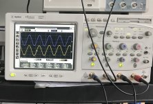
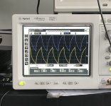
What does the picture of us feeding the amp square waves tell you? I don’t have a clue how to read that or what it means or if it indicates room for improvement. Is there any other testing I could do that might give you indications of the amp’s performance? I’d be much more than happy and grateful for every last shred of info and improvement possibilities you could give to me. ‘Preciate chà!
Freshly biased...
1mV signal @ 1KHrtz yields 1.176V left channel, 1.108 right channel
Difference of -23.35dB
Left channel gain of 61.4dB
Right channel gain of 60.89dB
Did we get that right? I know it’s not a lot, but when I switch to my Acūrus A150, I loose the ability to even it out as the only potentiometer is on my preamp. Is there a fix for it?
What does the picture of us feeding the amp square waves tell you? I don’t have a clue how to read that or what it means or if it indicates room for improvement. Is there any other testing I could do that might give you indications of the amp’s performance? I’d be much more than happy and grateful for every last shred of info and improvement possibilities you could give to me. ‘Preciate chà!
Attachments
1.176/1.108V is 0.517 dBV difference. Agrees with your total gain results difference.
The picture of you feeding square waves tells me that you don't have an anti-Riaa module to precondition them thus you see their expected shape transformation through the strong Riaa EQ in the pre-amp.
To bring the channel gains together, because this phono has no loop feedback to tweak ratios but relies on its semis transconductance match, the most practical way is to up R8's value a bit in the stronger channel, or to lower R8's value a bit in the weaker channel until you match them gains in the lab.
Is there any other testing I could do that might give you indications of the amp’s performance?
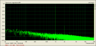
If your friend has a spectrum analyzer try test for an FFT clean in harmonic noise, of analogous THD % with comparable second to third harmonic ratio as that of my prototype's. It takes for the PCBs to be enclosed in a metal box and correctly grounded. Even the input signal's voltage divider must be shielded.
Conditions: Configuration LMC. 0.25mV RMS low noise drive signal. Division 1:200. Source impedance 5Ω. Output signal 300mV RMS for 61.5dBV gain. Reference FFT is attached. (Analysis points 131072. Sampling rate 48kHz. Wave format 24bit. Windowing Kaiser5. No averaging).
Attachments
Thanks for that Salas. I just wired up a divider and measured between the two channels of mine (still working on it). Output was a bit low at 0.8706 on one channel and 0.8646 on the other for a 0.06dBV difference. Close enough.
I'm in the process of building a raw supply and putting the shunts on the boards (powering them with a pair of golden reference PSUs right now at 35Vdc).
Regarding transformers, would a dual 32Vac secondary Antek 50VA be better than going with 36Vac? The 32Vac should give me roughly 43.8Vdc off of the rectifiers/filter caps? 36Vac would be ~49.5Vdc with that. My current transformer for testing is an 18-0-18 EI transformer, not sure how many VA, but not large. I guess I can try the raw supply with that and make a determination.
0.06dBV gain difference is more than good enough, its practically bang on. To know the absolute gain of your build based on its output with a test signal, you must also verify what exact mV you get after the divider. Some DMMs are good at 1kHz low mV AC scale resolution some are hopeless.
Because the generator has a source impedance, the divider also has input and output impedance, and the phono has a load impedance. Those can make a gen's test signal delivering weaker level than the expected division if loaded down. But for comparative gain purposes it does not matter.
As most USA home mains outlets tend to 120V AC from what I read in various reports here, then a 32V Antek should be fine. Just use a wire link or no more than 1Ω filtering resistor for RD/Link.
Its in series between bridge diodes output and the reservoir capacitor. That 3.3V loaded drop info may manifest as about 44V loaded raw DC result with those 27 Ohm RD. Still good. Each FSP's shunt reg/channel is going to draw about 100mA constant current.
Thanks, Salas. Looking at the board again it is clearly in series.

I didn’t have 27 Ohm, but I tested with 2 x 12 Ohm in series.
Works beautifully and shows 46.8 VDC at the output.
I measured 38mVAC on my DMM at the output as well, which I am interpreting as a proxy for residual ripple current. Does that result seem okay, or is this best measured on an oscilloscope? Filter caps are 4700uF Nichicon KG.
- Home
- Source & Line
- Analogue Source
- Simplistic NJFET RIAA